Hey All,
I have pair of vintage power transformers from circa 1948 Magnavox consoles. The transformers powered the amp as well as the preamp and tuner. The high voltage supply is 800 volts. The bias supply is 35. The heater supply is 5.5 volts.
My question is, are they safe to use in an amp today? The insulation on the leads is in surprisingly good shape. But can a 60+ year old power transformer be trusted? And is there any way to insure they won't cause damage or let the smoke out?
Kevin
or may not...
Best bet - take them to a motor rewinder or transformer shop and have them tested at the very lest for shorts and leakage to ground and interwinding shorts and leakage.
Smoke can be expensive...
BTW, its probably a centre tapped supply, so that's normally described by each phases voltage to the centre ie 400-0-400
If you only have a 5v heater supply, you will probably need an additional heater transformer (e.g. 6.3v)
Actually I have a 5.4 volt tap and a 6.7. Probably were intended to be 5.0 and 6.3. But my mains voltage runs high. The output tubes were originally 6V6's.
Actually I have a 5.4 volt tap and a 6.7. Probably were intended to be 5.0 and 6.3. But my mains voltage runs high. The output tubes were originally 6V6's.
Those measured voltages will come down, when current is drawn.
People forget that the long time North American rule for AC mains is 105 to 125 V. What's currently different is a higher average mains voltage.
If the old power trafos are electrically sound, powering a 6V6 or EL84 monoblock should be fine. My guess is that the rectifier was a 5Y3 and the 5 VAC winding is rated for 2 A. You can safely bring the B+ rail voltage up by using either a 5V4 or 5AR4, as those types draw 2 A. of heater current. Forward drop in a 5Y3 is large, while it's modest in a 5V4 and small in a 5AR4.
cellulose breaks down over time.
if the windings are in good condition, i suspect a short to case is less likely than a shorted turn.
i'd use them, but you might be surprised at how much power they draw at idle.
if the windings are in good condition, i suspect a short to case is less likely than a shorted turn.
i'd use them, but you might be surprised at how much power they draw at idle.
Thanks Again. The 1650n's are on eBay. If they sell I'm planning to buy a pair of Dynaclones. And Eli you are right. They were 5Y3's
And in general do you guys like tube rectification? From my earlier research I found it was considered a bad idea?
Kevin
And in general do you guys like tube rectification? From my earlier research I found it was considered a bad idea?
Kevin
it was not a bad idea before the advent of silicon rectifiers....nowadays you have better options....
Hey All,
Just for yucks I put the two 5Y3's back into the chassis and powered it up. I am amazed and humbled. The 5Y3's had 520 VDC output. And when I checked beyond the two 60 year old filter caps there was 1.26 volts ripple and, 0.00 after the second!
Just for yucks I put the two 5Y3's back into the chassis and powered it up. I am amazed and humbled. The 5Y3's had 520 VDC output. And when I checked beyond the two 60 year old filter caps there was 1.26 volts ripple and, 0.00 after the second!
Hey All,
If I have 520 volts is there some reason I couldn't use a simple voltage divider to get the 440 I need a high voltage supply and use the remainder for the bias supply?
If I have 520 volts is there some reason I couldn't use a simple voltage divider to get the 440 I need a high voltage supply and use the remainder for the bias supply?
Is there anyone here who could check my math? Triode's PA 135 power transformer for the Mark IV has 370-0-370 with a 55 volt bias tap at 150 MA. So is that 75 MA per side? And would 55/370=.1486 so that .1486x75=11.145 MA. So am I right in thinking that that bias portion of the winding could deliver 11.15 MA? So if I'm correct so far, I need a transformer that at 55 volts could flow at least 11.15MA? I've looked and the transformers I have found rated at 55 volts are rated at much more amperage than I need.
Enter Antek. Antek has an AN-0225 transformer that is 25 volts @ .5 amps. This is from two secondary windings that are run in parallel. If instead of parallel the windings were run in series, would their output then be 50 volts @ .25 amps? And if that is correct would the connections at the center of the transformer need to be grounded like a normal center tap?
Thanks for any help you could provide, Kevin
The amount of current needed out of bias supply is small. No way is the bias tap of a PA135 supplying 11 mA. RMS.
IIRC, your vintage power "iron" originally fed PP 6V6 circuitry. Even after factoring the tuner draw in, you are NOT on safe ground trying to power PP EL34 class tubes. Just because a 5Y3 is good for up to 125 mA. of B+ doesn't mean the power trafo is up to the task. If the console amp used 6L6s you would be safe.
You're on the right track looking at AnTek stuff to energize the bias supply, but you want a rail at least as "tall" as that used by Dyna. Wire the 2 secondaries of an AN-0215 in series and Greinacher ("full wave") double the 30 VRMS to get the bias voltage. 😉
Thanks Eli,
There is nothing in my Dynaco manual that provides a spec for bias tap amperage. I was just trying to figure a maximum possible amperage based on the ratios of the voltages.
These amps have two 5Y3's each
The power transformer fed a ppp 6V6 circuit (four tubes). I checked on the JJ website and if I'm understanding their specs they rate the EL34 at 100 MA for the plates and 14.9 ma for the grids with a 250 volt B+. For two EL34's, and 25 ma for the 7199, that's 256 ma. The 6V6 is rated at 45 ma for the plates and 5 ma for the grids. And these amps had 4 6V6's, so they had to be capable of at least 200ma for the outputs alone. You may be correct. I know there were a lot of little tubes in the preamp/tuner but their draw may not have added up to 56 ma. I have to either find an actual spec for this transformer. Or find a way to test it?
I looked at the Greinacher voltage doubler. But I'm not sure I know how to use it. He puts one end tap between the caps to ground. The other he splits between a 'forward' and a 'reversed' diode to get a positive and a negative voltage. Would I omit splitting the 'positive' end tap and only use the 'reversed' diode to give me the negative bias voltage? The AN-0215 is capable of .8 amps. The AN-0115 is capable of .33 amps, would that not be enough? Or is it the effect of the doubler that makes the 0125 necessary?
Thanks again, Kevin
I have to either find an actual spec for this transformer. Or find a way to test it?
diytube.com :: View topic - The Dumpster Transformer Topic
Hi,
I found some more information on the original Magnavox. The tuner/preamp section had one 6SK7, one 6SA7, one 6u5, and three 6J5 tubes. These draw a combined 55.3 MA. With the 200 MA draw from the 6V6's that's 255.3 ma total. If I'm right in adding the two EL34's and one 7199 at 256 MA for the Mark IV. The transformers, given Magnavox left any margin for error, should work. (Although I may be wrong.) These are pretty hefty transformers. They measure 3 1/4 x 4 x 4 1/2.
boywonder, I'll check out that link.
Kevin
Thanks boywonder, do you have a superhero sidekick?
By that method the secondary with 73.5 ohms/800volts gives me .092 volt/ohms. Which on their graph comes to, drum roll please, 255 MA! (With a choke input.)
I checked Triode's specs again for the PA 135 replacement they sell for the Mark IV. Their transformer is rated at 740 volts, but only 150 MA? Once again I don't understand tube math. If I added up 260 MA for the tubes how is it they can get away with only 150 ma's?
Kevin
Kevin,
OK, 2X 5Y3 and 4X 6V6 in the console amps = a hefty enough power trafo for a EL34 class monoblock. 🙂 There may be enough "sock" for the MK3 KT88 class.
I don't trust current production 5AR4s and NOS is prohibitively expensive. So, a single 5U4GB is what you use for rectification. Use either a current production EH or a NOS GE. Limit the capacitance in the 1st filter position to 40 μF. and use a 550 WVDC part. A Triad C-17X filter choke from Allied Electronics "sits" between the 1st and 2nd filter capacitor.
A Greinacher doubler consists of 2X caps. and 2X diodes. For a bias (C-) supply, the positive end of the cap. stack gets grounded. A bias supply has to be able to supply a small amount of current and the DC draw on a doubler should be limited to 1/4 the AC RMS value. I took no prisoners in suggesting the AN-0215. Use 220 μF./100 WVDC caps. in the doubler stack. A 1 A./100 PIV Schottky, like the SB1H100-E3/73, gets my nod for the doubler diodes.
Thanks Eli,
I think I'll take your advice and stick to the EL34's. That way I'm less likely to saturate the Hammond 1650n's. Plus, four matched EL34s are less than two KT88's. I can always build the Mark III's later.
Tube Depot sells the JJ 5AR4's for $14.95 and the 5U4GB's for $15.95. For the extra two bucks the extra amperage capability is worth it.
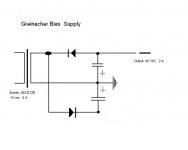
I've attached a drawing of the Greinacher doubler, I think. Is this correct? I wasn't sure what to do with the cap and the output from the 'positive' side of the rail. And I figured a drawing would make it easier for you correct it.
I think I'll take your advice and stick to the EL34's. That way I'm less likely to saturate the Hammond 1650n's. Plus, four matched EL34s are less than two KT88's. I can always build the Mark III's later.
Tube Depot sells the JJ 5AR4's for $14.95 and the 5U4GB's for $15.95. For the extra two bucks the extra amperage capability is worth it.
I've attached a drawing of the Greinacher doubler, I think. Is this correct? I wasn't sure what to do with the cap and the output from the 'positive' side of the rail. And I figured a drawing would make it easier for you correct it.
Attachments
If your going to use the 1650Ns, definitely go EL34 class tubes. Either EH 6CA7s or SED (=C=) EL34s will work well.
JJ's 5AR4, as is (sadly) all of their Octal production, garbage. Steer clear! I suggest you check in with Jim McShane for the tubes and (perhaps) other stuff. Jim burns tubes in and matches them properly. The man is as straight a shooter as can be found. His warranty is for real.
The polarity of the bottom cap. in the doubler stack is backwards. The center of the cap. stack connects ONLY to the power trafo. Ground that positive side! The Greinacher, AKA "full wave" doubler is 2 half wave rectifiers wired back to back. There is some justification for using "full wave", in that both halves of the AC cycle get used and that the ripple freq. is 2X the AC mains freq. BTW, I went back to the AnTek site. I was wrong about the AN-0115. It will be fine. 😉 I was thinking 30 mA. RMS, not 300 mA. RMS, which is the case.
Finally, if you don't already own 7199s, think hard about building with 6U8s, instead. The 7199 is scarce, costly, and fast going the way of the Dodo.
- Status
- Not open for further replies.
- Home
- Amplifiers
- Tubes / Valves
- Vintage power transformers