I bought a couple of dozen cheap Russion .1 uF teflon caps a few years ago and use them for bypasses but I've also used even cheaper film caps with virtually the same results.
I think the bottom line is try some low value bypass caps with the oilers and see if you notice or like the difference. If you don't hear a difference, leave them there, it won't hurt. If you do notice a positive difference, you could experiment with other values and types.
Kyle.
I think the bottom line is try some low value bypass caps with the oilers and see if you notice or like the difference. If you don't hear a difference, leave them there, it won't hurt. If you do notice a positive difference, you could experiment with other values and types.
Kyle.
Cascading Values
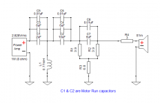
Hopefully these ( quick-pics ) add some clarity.

The motor-run cap values servicing C1 & C2 ( in the above pic ) would be 2uF & 10uF (as seen in the pic below ).

The size of C3 & C4 are ( roughly ) determined by the size of C7 ( which is 6 uF in this particular network ).
- "Roughly", means this is were experimentation comes into play / as long as the total capacitance is maintained for the Cascaded ( combined-value ) caps.
Only C1 & C2 are motor runs ( all the rest are poly's ).
I'd probably start with C1 being 4uF ( & of course, that choice will bump C3 down to 4uF because the combined value that must be maintained at that position is 8uF, from the original network ).
🙂
Hopefully these ( quick-pics ) add some clarity.
The motor-run cap values servicing C1 & C2 ( in the above pic ) would be 2uF & 10uF (as seen in the pic below ).
The size of C3 & C4 are ( roughly ) determined by the size of C7 ( which is 6 uF in this particular network ).
- "Roughly", means this is were experimentation comes into play / as long as the total capacitance is maintained for the Cascaded ( combined-value ) caps.
Only C1 & C2 are motor runs ( all the rest are poly's ).
I'd probably start with C1 being 4uF ( & of course, that choice will bump C3 down to 4uF because the combined value that must be maintained at that position is 8uF, from the original network ).
🙂
Attachments
Alternatively, I am also running model 19s and used the following combos to good effect:
2 x 4uF oil with a .1 TFE bypass in place of the 8uF C1
1 x 15uF oil with a 1uF film and a .1 TFE bypass in place of the 16uF C2
1 x 20uF oil with a 1uF film and a .1 TFE bypass in place of the 21uF C3
For C4 I used a 6uF film as it's a HF compensation cap intended to enhance the upper Freq range and I didn't want the softening of the oil caps.
My reasoning for the oil cap values was that they are readily available sizes from local HVAC suppliers and are the same types and brands that audio suppliers sell but at a fraction of the audiophile price. I'm so cheap.
I have also tried substituting both foil and wire air core inductors but went back to the Altec iron core types because they sounded better in my set up.
Just keep in mind that oil caps, like electrolytics will "dry out" in use over time. Of course the capacitance will go to hell in a hand basket. Most of my experience is with old guitar and bass guitar amps for the '50s and '60s. I've run across a few oddball, off brand guitar amps from that period with oil in paper caps in the construction and those were the first to replace as I went through these amps.
Sent from my iPhone using Tapatalk
Did you know that oil is not electrolytic, but an isolator and used as such?
Why in the altec circuit, the high frequency network is taken from after the first inductor and not from the input as it must?
Why in the altec circuit, the high frequency network is taken from after the first inductor and not from the input as it must?
Don't really know but ;
Classically:
(i) Bypassing an inductor ( of the proper size / usually 4 times the size of what you see here ) with a resistor yields a BSC circuit ( Baffle Step Compensation ).
(ii) Additionally, adding a small value inductor in series with a capacitor ( of the proper size ) will yield a bit of peaking EQ ( with the boost Q determined by how close together the Fc of the 2 poles are ).
Implementation:
Altec looks like they wanted ice cream with their cake.
The trouble is that their dual implementation is not particularly effective for either scenario, ( once that variable resistor gets set to an optimum resistance to drive the horn circuit ) .
🙂
Why in the altec circuit, the high frequency network is taken from after the first inductor and not from the input as it must?
You'll note that there is an Lpad from the input that goes to cap C1 (8uF) and to the junction of L1 and L2. The two Lpads are for the mids and highs and don't adjust either independently but instead, adjusting one affects both. C4 bypasses the Lpad and the two divider resistors R2 and R4 to provide compensation for the highest frequencies while allowing the mids and highs to have some adjustment without affecting the top end. I have removed this cap and the highs are severely rolled off without it.
Any horn the size of an 811 will have a rolled off top end and the compensation is necessary to balance the sound.
It's amazing what you can pick up from others after screwing around with the same xover for many years🙂 There's some very smart guys out there that live and breath Altec that are happy to share, thankfully!
Don't really know but ;
Classically:
(i) Bypassing an inductor ( of the proper size / usually 4 times the size of what you see here ) with a resistor yields a BSC circuit ( Baffle Step Compensation ).
(ii) Additionally, adding a small value inductor in series with a capacitor ( of the proper size ) will yield a bit of peaking EQ ( with the boost Q determined by how close together the Fc of the 2 poles are ).
Implementation:
Altec looks like they wanted ice cream with their cake.
The trouble is that their dual implementation is not particularly effective for either scenario, ( once that variable resistor gets set to an optimum resistance to drive the horn circuit ) .
🙂
The model 19 doesn't really need BSC with it's 30" wide baffle and horn loaded mids/highs. The xover is 1200Hz.
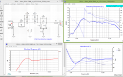
Here's a study of what that .3mH coil does to the HF circuit when the drive ( pot ) is toggled in value between 1R or 8R .
- The blue line is the 8 ohm end of the rotary pot.
( Click the pic for the readable version )
Note: this is not an Altec 811 horn, it's a PVR 152i Clone ( so the FR is not really indicative of what one would get with the 811b.

🙂
- The blue line is the 8 ohm end of the rotary pot.
( Click the pic for the readable version )
Note: this is not an Altec 811 horn, it's a PVR 152i Clone ( so the FR is not really indicative of what one would get with the 811b.
🙂
Attachments
Hi Earl. What are we looking at in the graphs? Is it the effect of the .3mH coil and either a 1R or 8R resistor in parallel? It seems that the 8R rolls the high end off an extra 6dB above 10KHz as it should as a BSC. However that's not what's required with the model 19.
The model 19 and other versions that use the 811 / 802 combination have an abundance of midrange but a rolled off high end, hence the use of HF compensation. BSC is more effective with typical modern speakers that have narrow baffles and direct radiator mids and highs. The large baffle of the 19s reinforces the mid bass projection and the oversized box seems to help with the low end as well.
Another Altec variant that benefited from the large baffle was the model 17 / 604-8G. Many of the newer implementations with narrower front baffles seem thin sounding in the lower mids and upper bass by comparison.
Those Altec guys were pretty clever overall.
Hi Earl. What are we looking at in the graphs? Is it the effect of the .3mH coil and either a 1R or 8R resistor in parallel? It seems that the 8R rolls the high end off an extra 6dB above 10KHz as it should as a BSC. However that's not what's required with the model 19.
My graph simply demonstrates the effect ( on the HF above @ 4K ) which occurs when the HF Level knob is rotated to ( mostly ) full on ( ie; CW versus CCW ) .
IME, BSC is a term reserved for bass & bass-mid frequencies even though the net effect ( here ) is accomplished in the same technical manner .
The model 19 and other versions that use the 811 / 802 combination have an abundance of midrange but a rolled off high end, hence the use of HF compensation. BSC is more effective with typical modern speakers that have narrow baffles and direct radiator mids and highs. The large baffle of the 19s reinforces the mid bass projection and the oversized box seems to help with the low end as well.
Another Altec variant that benefited from the large baffle was the model 17 / 604-8G. Many of the newer implementations with narrower front baffles seem thin sounding in the lower mids and upper bass by comparison.
Those Altec guys were pretty clever overall.
I'm aware that it seems virtually everyone will crank the M19 HF Level ( drive ) knob up to full on ( effectively making the .3mH coil a vestial/abandoned component since it gets bypassed by a very low impedance resistance ).
- In that regard the Altec engineers weren't able to anticipate current listening trends and ( as a result ) included a facility that most don't utilize ( OTOH, backed off, one can get a very reasonable X-Curve facsimile by turning that control CCW ).
Zilch in his Z19 ( remake of the N1201 network ) re-arranged the positioning of this .3mH coil and put it after the midrange padding ( this is a bit of a nod to how Tannoy implemented their HF trim within their older Coax networks ).
See;
🙂
Last edited:
Good morning Earl.
I realize that the schematic shows the simplified version of the Altec xover but it doesn't have the second connection to between the .3mH and 2.7mH coils which directs a portion of the signal to the LF driver. This is important because it affects the mids and bypasses the .3mH coil to an extent.
I've also played with the Z19 xover and in my opinion the best part is that you can bi-amp with it. I found it to have an over analytical presentation which I would assume is because of the tipped up highs. This may be a listening bias of mine and not an artifact of the design. I didn't measure that version, just listened. The biggest difference with the Z19 is the amount of attenuation the controls provide.
Also, while BSC may be said to make the bass stronger, it in fact rolls off the highs to do so. Passive components can't provide boost or gain, only cut, even if it is frequency specific. As you say, the net result is the same. It's a contouring circuit that gets more useful the smaller the baffle is. The model 19 with it's 30" baffle has a BSC freq of 152Hz I believe, which is outside the influence of the .3mH/8R combo. This is why Zilch was able to rearrange the Altec xover and still retain close to the same turnover point.
Interesting topic Earl but I think we've hijacked the thread🙂
I see you're from Toronto, we probably know some of the same audio riff raff. I'm from there originally as well.
No, you didn't hijack the thread, this is some very interesting info, keep it coming. After all, my goal is to build the best Model 19 crossovers that I can for my Altecs.
BillWojo
BillWojo
Correct! I was able to force more top end out of my 288s, but it was never great. So I rolled them off circa 7K and used a tweeter. For the nominal 700Hz-7KHz range I used, the motor run caps were superb. If they were soft on top, it did not matter to my application. A 2-Way like the M-19 might be a different matter.Pano,
I'm confident that you would have noticed this "softening effect" more-so, if you had been able to run your 288's fully up to their HF extremes ( without crossing into a tweeter, at 7K was it ? ).
I am curious about the "Soft on Top"" observations of motor run caps. I've heard it said more than once. What would it be? Do you think it's a frequency response and phase problem - or something else? Has anyone been able to measure the "softness" and show what it is?
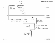
Yes nice thread,some philosophical musings from my experience,I have not heard a 19 in about 20 years,I owned some magnificents at that time,I also had 604e and k with the markawat crossover,which was better than stock ,I also tried the mastering labs crossover which had some improvements in the nearfield ,
As for caps and softness it could be plate resistance in the caps some guys swear by it even using 6 caps in parallel
Parallel Plate Capacitor
But using active crossovers on altec drives takes them to another level and you could rebuild some for the same price of pretty caps and coils,but finding the right amps takes years and money and some can be op am noisy
No softness issues at home(sorry)
Attachments
Hi zelgall,

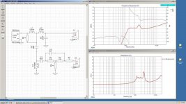
Here's a study of the expected ( max ) changes that one can expect when the .3mH coil is put into ( or out ) of the bass circuit ( using an Eminence woofer as a model standin ). The traces track either .5R or 8R .
One can see that the differential ( on the FR ) is limited to about a 1db change above @ 500hz.
If you typically drive you Horn Circuit output ( with the M19 network ) up to the max, then you are getting the trace that is slightly hotter than the blue trace.
Building the Z19 ( and therefore confiing the .3mH coil effects to the HF circuit ) means you are also getting the max output of the LF circuit.
Based on your comments that the M19 circuit doesn't sound as "clinical" as the Z19 ( if I understood you correctly and assuming you used identical components in your comparison / since the Z19 uses the same values as the M19 everywhere > where it matters ) that would point to the sound that you prefer as originating from the bass frequencies being forced through the large wire-wound, bypass resistor ( the 100 watt variable Lpad , in this case ).
That's an interesting thought.
🙂
Attachments

Last edited:
Correct! <<<SNIP>>>
I am curious about the "Soft on Top"" observations of motor run caps. I've heard it said more than once. What would it be? Do you think it's a frequency response and phase problem - or something else? Has anyone been able to measure the "softness" and show what it is?
The Altec 288 has such a superb ( natural midrange ) when used with motor runs that I forgive its failings higher up.
It really does lack "sparkle" & "air", even with all the cap finagling ( tricks ) that I can muster up ( such as adding bypass caps that go direct to the driver from the crossover's input terminal / ie; not-referenced to the other passives ).
Having said that, I never what to spoil what I have by adding a tweet to the mix ( & I have tried, since I own many Fostex bullet tweeters > SR vintage ).
I find the tweeter addition, spoils the great imaging that I'm able to achieve with out them.
Re Motor Runs (softness ) :
I previously mentioned Slew Rate ( or Transient Response ) being the audible difference to the more typical modern polys.
I'll still stand behind those thoughts / I don't think it's actual FR response ( though I'll admit I have never done an actual controlled test of 2 identical value caps, drawn from those two different types ).
🙂
An interesting page re oil (or more specifically PIO) caps: The "Sound" of Capacitors Not exactly news, since this is the sort of thing Altec, W.E. et al did a long, long time ago.
Hi zelgall,
Based on your comments that the M19 circuit doesn't sound as "clinical" as the Z19 ( if I understood you correctly and assuming you used identical components in your comparison / since the Z19 uses the same values as the M19 everywhere > where it matters ) that would point to the sound that you prefer as originating from the bass frequencies being forced through the large wire-wound, bypass resistor ( the 100 watt variable Lpad , in this case ).
That's an interesting thought.
🙂
You're cracking me up Earl🙂
Here's an Xsim shot of the M19 with an actual 802-8G on an 811 horn (FRD & ZMA measured with a WT2) - 416 response not shown because I didn't measure it in the cabinet as yet so I just have the raw driver data.
As for my preference in tonal balance, I enjoy an even handed presentation. In regard to the Z19 xover, I did say analytical rather than clinical but that's splitting hairs. Most visitors here tend to think my 19s are well balanced over all but I realize they are big, old style speakers and I run them with 300B or 2A3 SE amps which have a highish output impedance and hence a lower damping factor. When I hook up a SS amp the bass tightens up and the highs are more pronounced but in either case I wouldn't say that I'm a bass hound.
I do stand by my opinion that the stock crossover with new caps of the same value sounds better to me, in my room.
Perhaps some listeners are mini monitor or small equipment types that aren't used to full range sound and that skews their perception🙂
Attachments
<<<<SNIP>>>>I do stand by my opinion that the stock crossover with new caps of the same value sounds better to me, in my room.
<<<SNIP>>>
I'll go with that ( since I don't listen to any of these particular components or transducers )
The question then becomes;
What passive components does Bill buy ? ( so that he can best emulate that M19 sound )
After all, it's near impossible to source inductors ( E-Core type, I think ) like the original network uses .
Years back ( okay maybe 15 years ago ), I had read that an air-core coil bypassed with something like a 100 ohm resistor, was a decent start to the coil emulation ( I have never tried that though since I actively crossover & bi-amp the bass section of my speakers ).
🙂
Last edited:
- Status
- Not open for further replies.
- Home
- Loudspeakers
- Multi-Way
- Vintage oil and paper caps in crossovers?