It’s a nice planar tweeter with incredible off axis response for wide horizontal coverage. Any thoughts?
My thoughts have to do with why not simply do the so popular lately full range line array that we've seen threads on the last several years. You really have to prize that top octave and have good enough hearing to benefit from it to go another way. I'm going to assume that you do. I faced this same issue and ultimately decided that my hearing wasn't good enough to merit facing the complexities of a 2 way array and its own compromises. But I did go with a smaller and more expensive driver than TC9.
The only potential problem I see is CTC challenge in XO to TC9s. That is the same challenge one has in any 2 way array but here its worse because a 4 khz XO is recommended for the mini. The standard solution for CTC challenge is brickwall XO filters and if you don't mind them, then its likely a workable architecture.
And its a cost effective one as both drivers you mentioned are very reasonable.
The CTC issue could be reduced using Dayton DMA45s (1.5" driver) instead of TC9. IIRC, the DMA45 is also an $8 driver but you would need more of them, about 40 in a column.
At a 5khz cross from the TC to the PT, physical distance to the center of the PT would be 2.125 inches which is easily supported by the 2.72 inch wavelength.
It’s the amazing off axis response of the PT Mini that intrigues me for this build.....a pair of 24 driver arrays would have quite a coverage area and some serious output capabilities supported by some subs. The TC9 is prett constant in it’s directivity right up to 5khz so we’re talking consistent power response across the entire spectrum......something I have never experienced in a speaker before.
It’s the amazing off axis response of the PT Mini that intrigues me for this build.....a pair of 24 driver arrays would have quite a coverage area and some serious output capabilities supported by some subs. The TC9 is prett constant in it’s directivity right up to 5khz so we’re talking consistent power response across the entire spectrum......something I have never experienced in a speaker before.
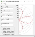
This is a sim of the pattern of the TC9?.......or the fwd lobe created by the crossover? Does this program assume a vertical alignment?..........if so, with what accuracy would that imply given the narrow vertical dispersion of the PT Mini?
Last edited:
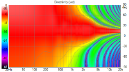
this is two point sources separated by the 2.125" you specified, equal levels, same phase, at 5 khz. Just a quick look at the directivity at 5 khz. Not a complete story by any means as the TC9 is narrowing while the mini is wide open but reason to suspect you would have a hole in your power response at XO, which could be narrowed by high slope XO filters.
Those tall vertical lobes are just about gone at 3800 hz, and the -6db BW is 60 degrees, BTW
One could get a much better look in Vituix with more effort. Lacking actual measurements, Vituix would/could use the actual piston diameters to compute directivity over the entire range.
Those tall vertical lobes are just about gone at 3800 hz, and the -6db BW is 60 degrees, BTW
One could get a much better look in Vituix with more effort. Lacking actual measurements, Vituix would/could use the actual piston diameters to compute directivity over the entire range.
Thanks!
So you’re saying the horizontal alignment vertical doesn’t matter in the case of this software? Would have have enter a phase overlap value created by the XO.....let’s say second order LR2?
My thought given the behavior of these drivers would be 1st order on the TC9?
So you’re saying the horizontal alignment vertical doesn’t matter in the case of this software? Would have have enter a phase overlap value created by the XO.....let’s say second order LR2?
My thought given the behavior of these drivers would be 1st order on the TC9?
Not sure what that means but am sure I'm not saying that, just singing the praise of Vituix without intending to infer anything in particular. Vituix goes beyond normal crossover programs in its ability to compute and plot directionality. Its worth your time to learn how to use it and its free. Too many features and capabilities to get into here.
TC9 certainly supports a first order low pass; likely the PT-mini wants a sharper slope high pass. I would let the simulation model and measurements instruct me in that regard, not hesitating to go higher order if needed to get good results.
TC9 certainly supports a first order low pass; likely the PT-mini wants a sharper slope high pass. I would let the simulation model and measurements instruct me in that regard, not hesitating to go higher order if needed to get good results.
Planar Tweeters on a baffle
The original question continues to interest me so ....
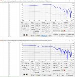
The Vituix diffraction tool allows us to take a quick look at how the Dayton planar tweeter(s) sum on a baffle.
Here is the PT-mini6 with my eyeball estimation of radiating surface dimensions from data sheet outline and photo:
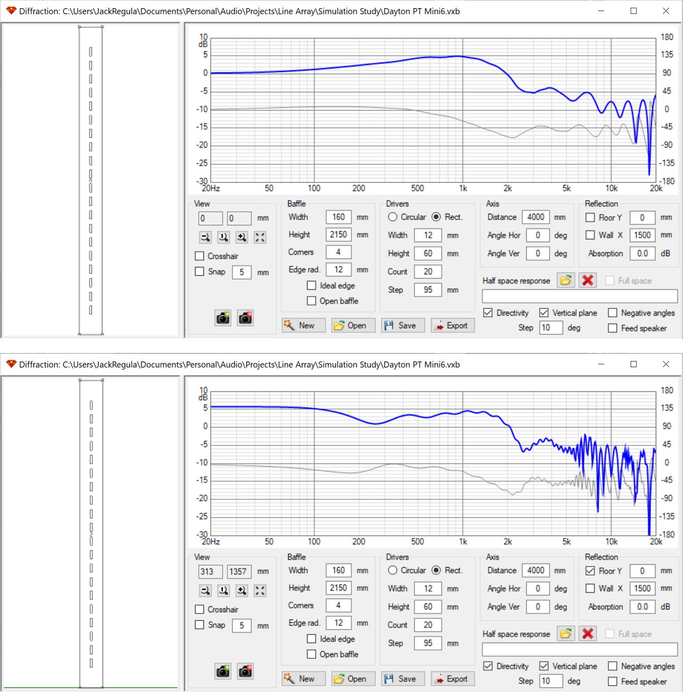
With rectangular sources, line array theory says that the radiating surface must be 90% of the spacing for a good approximation to a continuous line source. The mini comes in at about 75-80%. This shortcoming is apparent in the response that includes the floor reflection (but not the equally important ceiling reflection).
The frequency response ripples starting just above 1 khz are finite line array behavior. If it were a true infinite line array we would see a straight line. We see combing type nulls in the middle of the top octave. When the floor reflection is included, combing starts much earlier. This is starting to look ugly; you can look at my line array thread to see how it compares to a full range driver. Although similar in character, I think its better, certainly the combing starts later.
I thought it would be interesting to look at the other suitable Dayton planar; the PT2C. This is taller and has a smaller percentage gap between drivers. It costs 4X but you only need roughly half as many. Its wider than the mini but plays lower so I think it remains suitable.
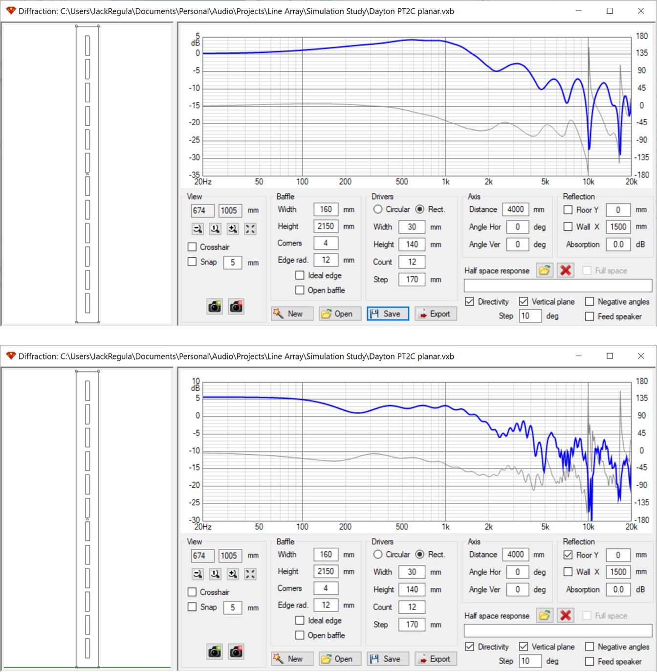
Without floor reflection, the mini looks better; with it, which I think is more realistic, the PT2C looks better.
The original question continues to interest me so ....
The Vituix diffraction tool allows us to take a quick look at how the Dayton planar tweeter(s) sum on a baffle.
Here is the PT-mini6 with my eyeball estimation of radiating surface dimensions from data sheet outline and photo:
With rectangular sources, line array theory says that the radiating surface must be 90% of the spacing for a good approximation to a continuous line source. The mini comes in at about 75-80%. This shortcoming is apparent in the response that includes the floor reflection (but not the equally important ceiling reflection).
The frequency response ripples starting just above 1 khz are finite line array behavior. If it were a true infinite line array we would see a straight line. We see combing type nulls in the middle of the top octave. When the floor reflection is included, combing starts much earlier. This is starting to look ugly; you can look at my line array thread to see how it compares to a full range driver. Although similar in character, I think its better, certainly the combing starts later.
I thought it would be interesting to look at the other suitable Dayton planar; the PT2C. This is taller and has a smaller percentage gap between drivers. It costs 4X but you only need roughly half as many. Its wider than the mini but plays lower so I think it remains suitable.
Without floor reflection, the mini looks better; with it, which I think is more realistic, the PT2C looks better.
Attachments
Yeah......looks ugly.
So if you inout your SB65 Driver as just a high frequency element, how does it fare in Vituix?
So if you inout your SB65 Driver as just a high frequency element, how does it fare in Vituix?
look at posts 47 and 48 for simulations and on the last couple of pages for measurements
http://https://www.diyaudio.com/forums/full-range/337956-range-line-array-wall-corner-placement-5.html
http://https://www.diyaudio.com/forums/full-range/337956-range-line-array-wall-corner-placement-5.html
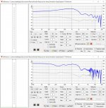
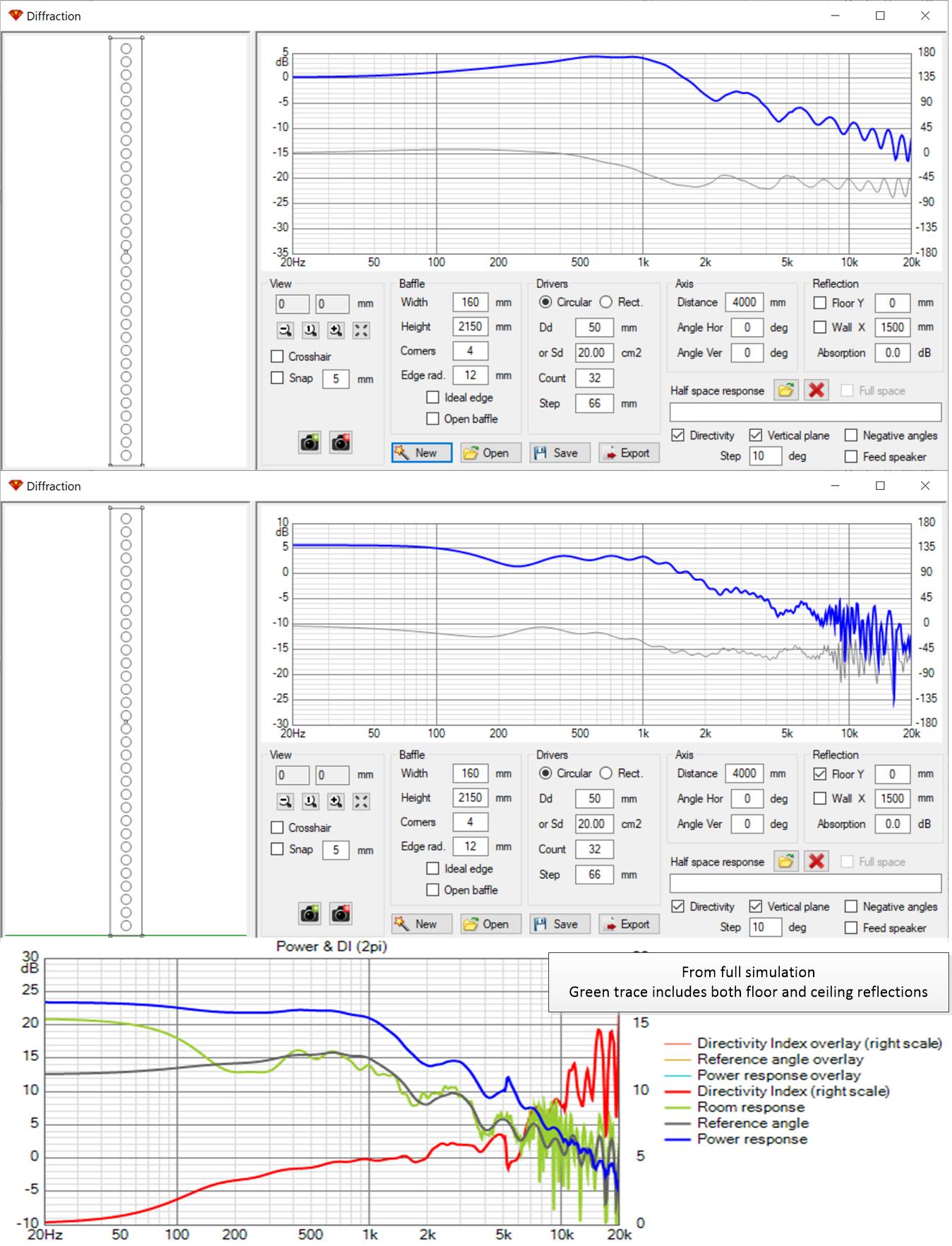
right but those Vituix screenshots show the same information in the frequency response traces. The main program takes the diffraction response of a single driver and computes the response of the full array; on-axis, listening window average, and with directivity plots
just for apples to apples I'll do a simple diffraction response later; in the middle of something right now
just for apples to apples I'll do a simple diffraction response later; in the middle of something right now
Here in the top two thirds of the image are the apples to apples screenshots of diffraction for the SB65 based solely on its piston diameter and spacing in my array. The lowest third shows in the green trace the computed room response with both floor and ceiling reflections from the full array simulation.
Attachments
Does the simulation take into account the fact that the mini PT and the PT2C elements likely will have vertical radiation performance different versus their horizontal performance?
These planar elements will trend toward reduced vertical radiation as frequency increases--vertical radiation trends toward the height of the active elements at the highest frequencies. I suspect that their actual performance in the near field would likely be improved with the planar units vs. an array of cone drivers. Of course floor and ceiling reflections will minimize if we design with floor to ceiling coverage from a straight line array.
My main issue with the mini PT units is their small size (requires more drivers in the array) and the gaps between the active elements when arrayed.
I wondered the same Jim, hence why I asked for the same sim with the Round fullrange for comparison. While there is no published vertical response graph, I’d be surprised if the vertical window differed much from typical ribbon and planar performance.
Given the dimensions, minimum radiating edge to edge would be 1”......less than any other planar/ribbon I could find. Creatively overlapping and drilling new mounting holes could reduce that by half....not sure if it would be worth the effort. Does the incredible published horizontal response beg the question?
Given the dimensions, minimum radiating edge to edge would be 1”......less than any other planar/ribbon I could find. Creatively overlapping and drilling new mounting holes could reduce that by half....not sure if it would be worth the effort. Does the incredible published horizontal response beg the question?
I exported a full suite of Vituix diffraction data for the PT2C and took a look at it. Vituix is indeed modelling different horizontal and vertical directivities in these simulations.
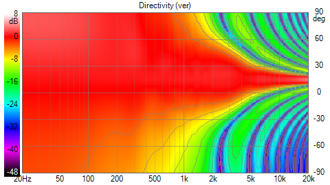
I went through the motions of a full Vituix simulation for PT2C array and the results were no better than for the diffraction tool generated plots already posted.
However, after some thought, I don't think Vituix can be used to simulate this type of array, at least not with any accuracy where the center to center distance of the planars is an appreciable fraction of a wavelength.
Typically, one sums point sources taking distance (attenuation and phase shift) into account. More sophisticated models (as Vituix is) might simply add an attenuation factor based on the directivity into each sum for each driver. But the model remains based on single beams from the centers of each driver's cone. No credit is given, so to speak, for the driver being tall and skinny, with only a small gap between drivers that is much less than the center to center distance that matters for circular pistons.
To get accuracy for a planar driver, especially a tall skinny one, I think you would need to model sound as coming from a fair number of points evenly distributed over its surface. I'm pretty sure Vituix doesn't do that so you should probably disregard the disappointing part of these results - they are likely false negatives.
I chose to look at the PT2C rather than the mini because its vertical coverage is around 82% whereas the mini's is only around 63% while 90% is recommended. The PT2C is thus more likely to give good results in an array.
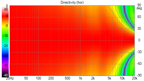
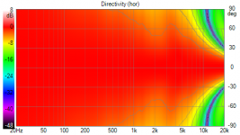
In that spirit, here is the array horizontal directivity as I don't think the aspect ratio issue affects the horizontal much, if at all:

Despite being much wider than the mini, the PT2C still gives a fairly wide beam, about 2x the beamwidth of my SB65 array.
I went through the motions of a full Vituix simulation for PT2C array and the results were no better than for the diffraction tool generated plots already posted.
However, after some thought, I don't think Vituix can be used to simulate this type of array, at least not with any accuracy where the center to center distance of the planars is an appreciable fraction of a wavelength.
Typically, one sums point sources taking distance (attenuation and phase shift) into account. More sophisticated models (as Vituix is) might simply add an attenuation factor based on the directivity into each sum for each driver. But the model remains based on single beams from the centers of each driver's cone. No credit is given, so to speak, for the driver being tall and skinny, with only a small gap between drivers that is much less than the center to center distance that matters for circular pistons.
To get accuracy for a planar driver, especially a tall skinny one, I think you would need to model sound as coming from a fair number of points evenly distributed over its surface. I'm pretty sure Vituix doesn't do that so you should probably disregard the disappointing part of these results - they are likely false negatives.
I chose to look at the PT2C rather than the mini because its vertical coverage is around 82% whereas the mini's is only around 63% while 90% is recommended. The PT2C is thus more likely to give good results in an array.
In that spirit, here is the array horizontal directivity as I don't think the aspect ratio issue affects the horizontal much, if at all:
Despite being much wider than the mini, the PT2C still gives a fairly wide beam, about 2x the beamwidth of my SB65 array.
Attachments
- Status
- Not open for further replies.
- Home
- Loudspeakers
- Full Range
- Vifa TC9 line array paired with Dayton PT mini?