Sure looks like M18s.
Here's it's big brother:
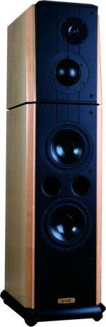
http://www.ruark.net/products/Sterling/excalibur.shtml
Looks like they're talking about M22s but with an inverted dustcap. Certainly looks like a Vifa driver.
M22s are the other option for a Vifa 3 way: 2 x M22, P13, XT25. Deep, potentially loud and with a decent vb.
Mos
Here's it's big brother:
http://www.ruark.net/products/Sterling/excalibur.shtml
Looks like they're talking about M22s but with an inverted dustcap. Certainly looks like a Vifa driver.
M22s are the other option for a Vifa 3 way: 2 x M22, P13, XT25. Deep, potentially loud and with a decent vb.
Mos
Vifa M18
Am about to finish (well one day) my boxes - originally were going to be 2 x scan 8545k (I had bought 1 pair but now cant afford another) , mid is the Vifa m13mi, hf planar.
Have changed the bass to Vifa m18 due to cost - they are excellent value!
Was going to be a straight forward 3way but have had a re-think & will probably do a 2.5way with the single m18 on the bass end - will try the Vifa m13mi (alnico) for mid but if its getting over extended down low will switch to either the Seas cb17rcyp or if I can find a pair of scan 8543s cheaply, or someone willing to swap for my 8545ks, - will have to wait & see on that one...
Anyway nice choice on the woofer - I wouldnt go with the d75mx - most mid-domes arent very good (except the ATCs, which ruark use but cost a fortune).
Have heard the p13 & its nice, not the last word on detail but nice.
my 2 cents...
a M18-xt25 combo (whatever the config, 2.5 way MMT or 2 way MTM or whatever) would require high order slopes on both sides. 3rd order i guess would be what you'd be looking at.
favouring lower order slopes why dont you use a classic midrange like the M10MD or MG10 MD from say 300 - 3k.
this way you could use second order slopes on the M18 or even use the M22 instead and also on the XT if you so desire. while i have not heard the xt25 i'd suggest the SS9500 as an alternate. i dont know if they are the same price.
the 75mm vifa dome mid is not really useable till about 600Hz or so even higher by some accounts.
if were set on a 3 way using the M18 and XT I'd go for a W MT W config or WW MT config using the M18, M10, and XT.
the cones are better matched. with 2 m18s u dont need the bass of the P13 and by the way I really prefer vifa low damping surrounds to the high damping surrounds.
I'll add 2 cents as well
I have buildt a 2-way mtm with the M18 & xt25 about one year ago. I buldt the cabinets of 30 mm MDF with 20 mm birch plywood panels on all sides. A good 50 mm wall thickness, I might add!
I made them 55 litres tuned to 32Hz. - Just as predicted by you guys. I must say I'm most impressed by the bass capability of these babies. The xt's are exelent too. Imageing is stunning as well.
I have some troubble (still) with the cross over though. I use a 24dB with impedance correction for the xt's and a 12dB for the M18's. I find the highs to be a little to 'bright'. Maby because I cross over just below 2000Hz. Also, the mid bass is very dominant. I tried to 'simulate' baffle step compensation by turning up frequencys below 500 Hz, using my computer, and this seemed to solve the problem. Considering that, I think baffle step compensation should be used in the cross over.
The xt's should be good down to 1500 Hz according to the data sheet. But, I'm not shure I would go just that low. I would stay clear of the 3000 Hz region vital for voice reproduction, if possible. What do you think of this? How low can I go?
To thomas
You could convert your MTM to a 2.5 way.
Basically crossover the top M18 to the tweeter, you'll need to
pad down the tweeter and new components for the top M18.
The other M18 is rolled off much lower with a single inductor,
around 300hz ? This will give you full baffle step correction.
JMO but i think MTM's suffer from midrange glare due to the
double sources of upper midrange creating a line source effect.
Lack of baffle step correction certainly won't help.
Another advantage of a 2.5 way is that the unit handling
the midrange is not 'slugged' by the BSD correction inductor
or end up with a resistor in series with it (the bypass resistor
of the BSD inductor). Only disavantage is that your forced to
go with full as opposed to partial, baffle step correction.
I don't think its a good idea to go any lower with the tweeter.
") /sreten.
/sreten.
You could convert your MTM to a 2.5 way.
Basically crossover the top M18 to the tweeter, you'll need to
pad down the tweeter and new components for the top M18.
The other M18 is rolled off much lower with a single inductor,
around 300hz ? This will give you full baffle step correction.
JMO but i think MTM's suffer from midrange glare due to the
double sources of upper midrange creating a line source effect.
Lack of baffle step correction certainly won't help.
Another advantage of a 2.5 way is that the unit handling
the midrange is not 'slugged' by the BSD correction inductor
or end up with a resistor in series with it (the bypass resistor
of the BSD inductor). Only disavantage is that your forced to
go with full as opposed to partial, baffle step correction.
I don't think its a good idea to go any lower with the tweeter.
/sreten.ok 2 more cents...man this will soon add to a full dollar!
i agree with sreten. the large inductor in the LR BSC is a heaache for midrange. go 2.5 way. your net sens will be the same.
the XT would prefer a XO above 3k but given that you have M18 what i'd do is roll one m18 at 2.2k-2.5k (also have impedance comp) or there abouts at 12db. let the XT roll at about 3k 12db too. should be ok. use LSP cad to siumulate XO.
the second M18 at 300hz 6db wil only require one single resistor (as well as impednace comp).
i find impedance comp on woofers makes a lots of sense.
not liking part count...
the lower M18 will have only 3 passive parts, the upper M18 4, and the XT 4-6
every part adds a bit to the music and takes some music away souse as few parts as possible. in fact the imp comp and parallel cap in the upper M18s ckt can be replaced by a simple RC combo. LSPcad lite will help with this.
use google do find LSPcad lite.
Hi, Thomas
That seems like a pretty good tuning/vb for those M18s.
Tell me, how does the bass output/tunefulness sound when you give them a bit of power? Would you say the bass seems to sound, um, constrained, compressed? At high inputs does the bass still seem tuneful or do things get a bit mixed up?
For what it's worth, I agree with Navin and Sreten, a 2.5 makes sense. I really like the idea of a .5 way speaker config being used for BSC.
Navin:
Can I have your opnion of the Vifa M22? You've mentioned it in several posts. You see, an alternative to 2 x M18, P13 and XT25 is 2 x M22.
Mos
for Mos
this may give you some ideas regarding twin 8's :
http://www.deadwaxcafe.com/vzone/david/david.htm
/sreten.
this may give you some ideas regarding twin 8's :
http://www.deadwaxcafe.com/vzone/david/david.htm
/sreten.Hi Thomas,
Try setting crossover at 2,500Hz, and using third orders on all drivers.
This will enhance imaging, remove the bloated midrange, and make life a little easier for the XT.
Correct for impedance variation with a Zobel. Important for the amp; helps with phase shift and improves imaging.
Cheers,
Hugh
Try setting crossover at 2,500Hz, and using third orders on all drivers.
This will enhance imaging, remove the bloated midrange, and make life a little easier for the XT.
Correct for impedance variation with a Zobel. Important for the amp; helps with phase shift and improves imaging.
Cheers,
Hugh
sreten, navin, Hugh
Thanks alot for good advice! Today, when I got home I calculated a new filter based on your inputs and went out and got the parts needed. I just finished soldering them together and are listening to the results as I write this.
I made the filter to be a 3rd order Butterworth for the Xt and M18 crossed at 2500Hz. The lower M18 is crossed at @450Hz using a first order filter. The highpass got the impedance correction network I yanked from the old filter. I made a new attenuation circuit also.
Reults! We want results!
I must say the sound improved. - Alot!
The treble isn't so bright anymore. Now it got a very smooth and pleasing sound. Soundstage seems clearer also, but I need to listen to more CD's to say more about this. The bass improved alot also, thanks to the baffle step compensation.
This combination is a winner!!!!
Mos,
Driving my gainclones just below clipping (3886 based), all seems fine to me.The sound is well behaved and there are no funny looking cone excursions here. Ofcourse, the speakers can take doubble or tripple the power if I had it. I don't, so I can't really say how they behave at insane levels. I gave them the 1812 test (yes, the one from Telarc). I listened at different volume levels and I could not hear any change in imageing or 'clearness'. I'm not excactly shure what you meen by tunefulness, but it seems to me the sound is pretty much the same at different levels (except louder, ofcourse).
Glad that things have improved !
I notice AKSA advocates 3rd order on each driver - but to me
this is like saying "apples, pears and oranges please" to a
greengrocer, you'll just get a quizzical look back.
There's such a huge range of possibilities within "3rd order".
I'd investigate designs that use both drivers and have measured
results for each driver and the crossover used before settling
on the final arrangement.
Then finally tweak the lower bass unit frequency to suit.
/sreten.
I notice AKSA advocates 3rd order on each driver - but to me
this is like saying "apples, pears and oranges please" to a
greengrocer, you'll just get a quizzical look back.
There's such a huge range of possibilities within "3rd order".
I'd investigate designs that use both drivers and have measured
results for each driver and the crossover used before settling
on the final arrangement.
Then finally tweak the lower bass unit frequency to suit.
/sreten.Hi All
Thomas, congrats on your improved sound. This is what it's all about: real-time, online help, experimentation and results!
Re what I meant by tunefulness: I mean when you can hear each bass note as a well defined sound or note (bad production notwithstanding). Often, in my experience, less than well designed drivers will start to loose their ability to stay linear re tunefulness as the inputs get greater. Or, in other cases, drivers will have a "sweet spot" where things sound great but then at lower or higher inputs the sound disintegrates.
I'd be interested to know how the sound is affected if you adjust your .5 way inductor.
Regards
Mos
Mos,
I can't hear any change in character of the sound at different levels. I believe this is what you mean, right? The driver seems quite sturdy in build quality. I believe this quality is reflected in the sound, which are just great. The midrange is exelent and are not affected by powerfull bass at the same time.
I will play around with the 0.5-way inductor a bit. My speakers are 27 cm. wide and have a calculated baffle step at 425 Hz. Time is short this week, so I have to wait untill some time after thursday, at least . I will report my results here when done.
What version of the M18 are you planing to use? I can only see one (M18WO-09-08) at danish sound technology's home page, but I have seen at least three versions. Mine is a M18WH-08-08 and have slightly different parameters. SPL plots seems nearly identical though, except the WO got a little notch about 1400Hz.
Varying the 0.5 inductor
Basically will not affect the bass much, it not like a 2 way where
the amount of compensation is variable, you are stuck with the
full 6dB's worth of compensation.
If the inductor value is too high a depression will form in the
200Hz to 800hz region.
If its value is too low a hump will form in the 400 to 1.6k region.
/sreten.
Basically will not affect the bass much, it not like a 2 way where
the amount of compensation is variable, you are stuck with the
full 6dB's worth of compensation.
If the inductor value is too high a depression will form in the
200Hz to 800hz region.
If its value is too low a hump will form in the 400 to 1.6k region.
/sreten.hi navin,
Having an R in parallel with the inductor is common for
normal baffle step correction, but as far as I know not
common for the 0.5 configuration.
It may allow an optimum matching of the slope of the BSC,
but it will feed through midrange that will not be rolled off.
In the low treble it will have more output than the driver
that you are using for midrange !
So IMO using a parallel R would require you to use an
additional capacitor for a very overdamped 2nd order
filter on the 0.5 unit.
If your tuning by ear I'd suggest its far too complicated,
you need measuring equipment and or good modeling
software and driver information for this sort of thing.
/sreten.
Having an R in parallel with the inductor is common for
normal baffle step correction, but as far as I know not
common for the 0.5 configuration.
It may allow an optimum matching of the slope of the BSC,
but it will feed through midrange that will not be rolled off.
In the low treble it will have more output than the driver
that you are using for midrange !
So IMO using a parallel R would require you to use an
additional capacitor for a very overdamped 2nd order
filter on the 0.5 unit.
If your tuning by ear I'd suggest its far too complicated,
you need measuring equipment and or good modeling
software and driver information for this sort of thing.
/sreten.- Status
- This old topic is closed. If you want to reopen this topic, contact a moderator using the "Report Post" button.
- Home
- Loudspeakers
- Multi-Way
- Vifa M18 in 3way?