Hello,
A video of the following description can be seen here:
https://www.youtube.com/watch?v=Pcfv-frF8eA
Long story short: I had to match the VFD circuitry from a Sony CDP-103 to a CDP-502. Both players are from the same age and share the same mechanism controls. All connections, voltages, measurements on the scope (like clock cycles) seem to be o.k., as described in the service manuals.
But all segments of the VFD are illuminated. One can observe this in the beginning of the video.
When the player is switched on, all segments are illuminated from the first second.(But they should be black)
Then, there is additional brightness added to the segments that are "corectly" illuminated. (Like display of time etc.)
So data is displayed correctly, but somehow the segments do not become black where/when they should be.
The only signal in question seems to be the RESET-signal.
It is not described in the CDP-103 service manual but in the CDP-502:
1,5 seconds no voltage when the unit is powered on, this seems
to be the moment, when all segments are lit.
But the voltage is according to the manual, 5 V.
I assume there is really something wrong with multiplexing, maybe someone has advice?
Thanks a lot and all the best,
Salar
Hi Salar,
Have you looked at the multiplex signal with a 'scope? This would be very useful.
-Chris
Have you looked at the multiplex signal with a 'scope? This would be very useful.
-Chris
Hi Chris!
I did. I have no experience, but the signal for the segment driver looks noisy.
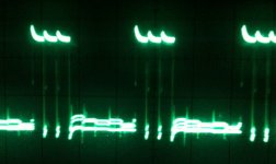
Some photos, I hope they will be attached in the correct order:
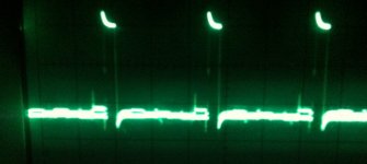
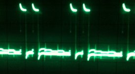
They show the display and the corresponding scope signal, around 1ms and 20V.
The scope signal was taken from segment "a" only (Pin 30 of the VFD)
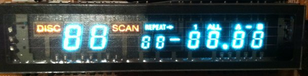
1) Display during stop.
2) Scope during stop
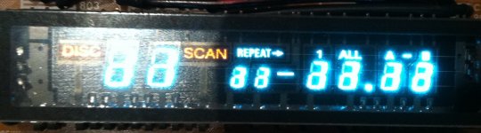
3) Display during play (Hard to see, some segments are now brighter)
4+5) Scope during play.
6) The display with +32V supply voltage removed from the VFD-Drive.
The segments "a" to "g" (for the digits) are still lit, but not the segment h(For the
typos like "Disc" "Scan" etc. I assume nothing should be lit, as long as the VFD drive gets its +5V supply only?
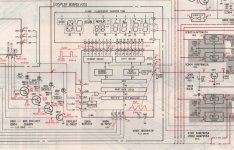
7) Excerpt from the service manual of the CDP-103 from which the complete circuitry, master control, VFD drive and SIRCS decoder, are taken. Besides the noisy
segment signals, all other measurements seem ok according to the service manual. Voltages, also the noisy ones, are correct.
Also pushing the two skip buttons distorts the display. They are, like all other buttons, attached to the multiplexing signal.
All the best,
Salar
I did. I have no experience, but the signal for the segment driver looks noisy.
Some photos, I hope they will be attached in the correct order:
They show the display and the corresponding scope signal, around 1ms and 20V.
The scope signal was taken from segment "a" only (Pin 30 of the VFD)
1) Display during stop.
2) Scope during stop
3) Display during play (Hard to see, some segments are now brighter)
4+5) Scope during play.
6) The display with +32V supply voltage removed from the VFD-Drive.
The segments "a" to "g" (for the digits) are still lit, but not the segment h(For the
typos like "Disc" "Scan" etc. I assume nothing should be lit, as long as the VFD drive gets its +5V supply only?
7) Excerpt from the service manual of the CDP-103 from which the complete circuitry, master control, VFD drive and SIRCS decoder, are taken. Besides the noisy
segment signals, all other measurements seem ok according to the service manual. Voltages, also the noisy ones, are correct.
Also pushing the two skip buttons distorts the display. They are, like all other buttons, attached to the multiplexing signal.
All the best,
Salar
Attachments

Last edited:
I have two players to salvage the VFD Drive from (Mitsubishi M5494OP)
soldered them in them, the result is the same.
The VFD drive gets data from the master control which communicates with the mechanism control.
The master control and mechanism control are microcontrollers. (MSM6404A)
They differ in the code number. I assume they are dependent and both must be changed, but I changed the master control only.
Changed the mechanism control as well. Now mechanism control and master control fit but no difference, still all segments lit. Thus maybe the master control is out of order?
It also became erratic about remote control commands, sometimes they work, sometimes they don´t.
It also became erratic about remote control commands, sometimes they work, sometimes they don´t.
So, I changed the master control to make sure the IC is not blow.
(Com,es Handy to have 2 Players with the same chipsets.)
But no Change.
So there must be something I might have overseen, but I checked all connections several times. Also, besides that there is an Inverter for the reset Signal, all connections are direct. Besides the fact that one might mix up Connections, everything is pretty straightforward.
I also assume that the IDP signal for the data Display is not based on the fact wethet the Drivers for the symols and gatters are have a negative or positive suplppy voltage.
In all chip-variations I tried, some flickering can be seen.
Also all digits are lit up when powering on, they should be black during the
first 1.5 seconds of powering up 😕
Its always nice to have conversations with oneself in a forum...
As described before, I tried to swap the worn VFD Display (and necesssary circuitry for dtiving the display ) of a Sony CDP-502 with the display of a CDP-103 or CDP 102.
Basic idea: Mechanisms and microcontrollers are the same (but differ in code numbers). The only important part seemed to be the master controller that communicates with the display.
The first mod that had to be done was to replace the 4mHz xtal of the CDP-502 with an HC74 inverter that is fed by the bitclock.
Also a +32 V power supply had to be made.
After adding the master controller from a CDP-103, key commands and remote worked from the beginning. But the display of the CDP-103 did not, all segments are illuminated and flicker.
Swapped master and mechanism controllers since then and tried different variants, but the results were the same. Also, if not blow by deslodering / soldering, the mechanism controller of a CDP-103 does not work in a CDP-502.
After rechecking all connections and swapping microcontrollers it seems obvious to me that despite the same chipsets and mechanisms each model got their microcontrollers individially programmed and they are not interchangeable between models of the same age.
Could anyone confirm this?
All the best,
Salar
- Status
- Not open for further replies.
- Home
- Source & Line
- Digital Source
- VFD not working correctly - all segments illuminated