Here's one with Peerless 10" slim, don't mind the translations 😀
Google Kaantaja
You can make a 75 or 60 liter version. Bigger one will reach down to 20hz.
Wow, that is very smart. And very very slim.
Great website, tnx for that. Found this one also:
Kaiutinrakennusohje - Purismi - neljan sahkoisen osan kaiutin 6,5-tuumaisella koaksiaalilla - AudioVideo
So, have you chosen or not yet?
I think about choosing a different spot in the room that doesn't ask for a case that slim😎
Hi PCSoldaat,All
I suggest using a 2 x 2 Watt Amp.😉
b🙂
Could you please explain what you actually added. You clearly are more experienced than me. Teach me, please.
Could you please explain what you actually added. You clearly are more experienced than me. Teach me, please.
Hi PCSoldaat,
You published a couple of non-closing Simulations= Results (after hitting the Calculate button) that tell almost nothing about what you are aiming at when not providing important information, I.e all other possible Screen Plots (+ the underlying ones that are all essential when clarifying the Results and making interpretation of your Design possible).
But One was a Posting of Transfer Function Plot = 'narrow bag - horn response 4.png' at Eg = 2.83 V Rms.
So, I just increased the Voltage to 3.58 V(= ~0.82W/Driver) as this Voltage makes the Excursion to reach 2mm at ~ 40 Hz.
Then if a Power Amp using 2 x 2 V Rms= 4V Rms, a margin of ~20 x log (4/ 3.58)= ~0.96 dB occurs or ~ +1 dB Voltage handling margin for the Power Amp, of course a minimum Head-Room but IMO enough if using this Power Amp.
You're mentioned a 2 x 25 W Amp to be ‘ little to small’ but is way to capable as the Eg margin will be 20 x log (14.14//3.58)= ~11.93 dB enough to push the displacement to +- 8 mm at 40 Hz I.e. if you toying carelessly with the Power Amp Volume Control.
b 🙂
PS: My Picture: I added Semi Inductance Parameters but everything else is from HR besides the Calculation of Le 1k that was taken from the provided Driver Impedance Plot.
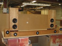
...and mount the driver(s) on the left and right sides...
Worth emphasizing. Anytime you use more than 1 woofer in a box, mounting them push-push and tightly coupling them has tremendous benefits in terms of reducing box load (dramatically) due to active reactive force cancelation.
As long as the drivers go low, and you have lots of width and height, and you can fit the drivers into the box, you can get whatever volume is required. Volume is the key box aspect that determines how low it can go.
I have used the (no longer available) SDX7 in slim woofer boxes. Designed such that when wall mounted they would not extend beyond the front of his TV. The wife objected when he got them and they were used behind the couch. With a touch of EQ they are happy to 25 Hz or so sealed. You won’t get 2 in a slim box push-push thou.
Visaton KT100V — you miight be happy with sealed and some EQ but a vented box can get below 30 F6, below mid 20s F10 (12 litres per driver). No xMax given so only a guess as to when you’d run out of steam. At 80 dB sensitivity it is clear they have really pushed the Fs down for such a small woofer. At least 6 per side is a wild guess at how many would be needed, but that depends on how loud you need. Ignoring material thickness (loaded push-push 15mm quality plywood should be suffiicient 9maybe even 12mm), a depth of about 12 cm should be doable.
dave
Attachments
Made a QWTL with 2,6 m length and a little taper for a double 4" Visaton driver.\
Doesn’t seem to go any lower than the reflex (you need to add some damping to the model to make the modeled FR easier to understand.
You do not seems to have taken advantage of dramatic taper to reduce line length or mounted the drivers push-push.
dave
A shallow 10" or 12" woofer will obliterate a pair of fours.
Indeed. A rule of thumb is that a it takes 2 4” to equal a 5.25", which has to be doubled to equal a 6.5”, double again to 8, again to 10.
That makes a bald-face estimate of 32 4” to equal a 10”. And the 10” will often go lower.
dave
...F3 is around 25 Hz...
Toole has shown that F3 is a meaningless value to the human ear/brain. Much better to look at F6/F10. You also want to have a model that does not go ruler flat till it starts rolling off. You need to account for room gain.
dave
Hi PCSoldaat,
You published a couple of non-closing Simulations= Results (after hitting the Calculate button) that tell almost nothing about what you are aiming at when not providing important information, I.e all other possible Screen Plots (+ the underlying ones that are all essential when clarifying the Results and making interpretation of your Design possible).
But One was a Posting of Transfer Function Plot = 'narrow bag - horn response 4.png' at Eg = 2.83 V Rms.
So, I just increased the Voltage to 3.58 V(= ~0.82W/Driver) as this Voltage makes the Excursion to reach 2mm at ~ 40 Hz.
Then if a Power Amp using 2 x 2 V Rms= 4V Rms, a margin of ~20 x log (4/ 3.58)= ~0.96 dB occurs or ~ +1 dB Voltage handling margin for the Power Amp, of course a minimum Head-Room but IMO enough if using this Power Amp.
You're mentioned a 2 x 25 W Amp to be ‘ little to small’ but is way to capable as the Eg margin will be 20 x log (14.14//3.58)= ~11.93 dB enough to push the displacement to +- 8 mm at 40 Hz I.e. if you toying carelessly with the Power Amp Volume Control.
b 🙂
PS: My Picture: I added Semi Inductance Parameters but everything else is from HR besides the Calculation of Le 1k that was taken from the provided Driver Impedance Plot.
Wow, I'm need to read this another 10 times😱
Thanks a lot!
Toole has shown that F3 is a meaningless value to the human ear/brain. Much better to look at F6/F10. You also want to have a model that does not go ruler flat till it starts rolling off. You need to account for room gain.
dave
Anyone with an EQ can prove that down low we can barely hear F6, so F10 should be the standard.
+1
GM
Indeed. A rule of thumb is that a it takes 2 4” to equal a 5.25", which has to be doubled to equal a 6.5”, double again to 8, again to 10.
That makes a bald-face estimate of 32 4” to equal a 10”. And the 10” will often go lower.
dave
Hmm, got a few too many doublings 🙁, i.e. based on browsing a variety of 4"/ 54.1 cm^2 avg, 10"/415 cm^2 avg:
415/54.1 = ~7.67 drivers, so round up to 8.
FWIW, the ROT I use is based on effective diameter is 2x area = 1.4142x larger dia., so a 5.5" [5.657" calc'd] comes closest to [2] 4" or move up to 6" for much more selection and double dia. to quadruple area = 8"/[4] 4" and another doubling puts us at 11.31", which some might bump to 12", so for tight budgets, large arrays, best to use their respective Sd to calculate what's needed since this ROT has gotten too far off to continue.
GM
GM,
Thanx. I know, but doing that is a lot of work. I just wanted to illustrate.
1 too many doublings would mean 16 drivers — 12 litres x 16 = 192 litres.
dave
Thanx. I know, but doing that is a lot of work. I just wanted to illustrate.
1 too many doublings would mean 16 drivers — 12 litres x 16 = 192 litres.
dave
- Home
- Loudspeakers
- Subwoofers
- Very slim subs?