This amp is stellar! It is the quietest amp I ever heard.. dead silent. No turn on thump.. I'm a little worried about it running away hot. When it gets warm. it idles drawing more current then when it's cold. I'm only giving it 13 amps right now. Imagine when I hook it to 500 amps. What's the best way to test the vbe?
I love this thing! I listened to it for the last 4 hours..
Thanks to all you contributers!
Evan, if you or anyone else has another set of boards..
I love this thing! I listened to it for the last 4 hours..
Thanks to all you contributers!
Evan, if you or anyone else has another set of boards..
Attachments

I'm happy there are people on this earth like you Hugh. And everyone else that positively adds to this community.
I might should start a new thread with this question, but what kind of solder and Flux do you all use? I had a big roll of RadioShack solder and Flux I recently ran out of. I bought some crap on Amazon that is garbage. Regardless of the Flux I use it is dirty and Grey. Headers break lose as soon as you plug one up. I chased bad solders all over the last boards I built using the junk.
There must be a quality solder with no clean Flux out there. I'm apprehensive of using acidic Flux as I destroyed 8 output fets using a spray cleaner once.
How do you clean your boards?
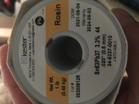
I agree with evanc. Kester "44" solders great. I like SN63PB37 in 0.031". No need to clean the flux, but it does clean easily with isopropyl alcohol (rubbing alcohol) and a toothbrush. I also use Kester 186 flux pen to apply liquid flux prior to soldering.
Hello Quasi enthusiasts,
Having completed the FH9HVX amp and the Xmas amp, I am moving on to the VSQA. To start, I recently gutted an old Yamaha 5 channel amp that I have had for years, but not used that much. Among lots of spare parts I think I can use, there was these heatsinks. From the manual the 2 main channels were rated for 135W each, so I thought I could use these heatsinks for the Quasi. The sinks measure 300mm x 110mm x 40 mm, with a 6mm base. They are light with a lot of surface area. Comments please and thank you.


Having completed the FH9HVX amp and the Xmas amp, I am moving on to the VSQA. To start, I recently gutted an old Yamaha 5 channel amp that I have had for years, but not used that much. Among lots of spare parts I think I can use, there was these heatsinks. From the manual the 2 main channels were rated for 135W each, so I thought I could use these heatsinks for the Quasi. The sinks measure 300mm x 110mm x 40 mm, with a 6mm base. They are light with a lot of surface area. Comments please and thank you.
Kokanee,
That would be a terrific heatsink, should be enough for two channels!
Show us when you have the amp running!
Hugh
That would be a terrific heatsink, should be enough for two channels!
Show us when you have the amp running!
Hugh
Thanks Hugh, I also have a smaller set of heatsinks from a Rotel amp that was good for 40 W/channel continuous output, that measure 140mm x 50mm x 35mm, with a base thickness of 7mm. See pic attached. Not sure if these are a bit on the small side.? I will be using 42V rails and a FQA40N25 for Q6 and MJL3281 for Q7.
Thanks for your comments.

Thanks for your comments.
Hi, I think those will be alright. I made a similar build with heatsinks about that size, and while it gets pretty warm, it's not too hot.
Myles,
I agree with jvhb. The Quasi is AB, so idling will be low dissipation, and music does not give high dissipation unless it's continuous, crescendo orchestral (or rock!).
Hugh
I agree with jvhb. The Quasi is AB, so idling will be low dissipation, and music does not give high dissipation unless it's continuous, crescendo orchestral (or rock!).
Hugh
Thanks jvhb and Hugh, the way I was thinking about this was that if one uses transistors that can handle higher power, then the dissipated heat will not be as much as if you are using a lower power transistor that has to work harder. If I am wrong, please correct me.
Yes, Myles, but the dissipation on TO3P and TO247 will be pretty much the same at any audio output.
What is important is the connection between the device, the mica washer and the heatsink.
Even a TO3P will be fine in this role; it's only 42V rails, not 50V or more where dissipation becomes an issue.
Hugh
What is important is the connection between the device, the mica washer and the heatsink.
Even a TO3P will be fine in this role; it's only 42V rails, not 50V or more where dissipation becomes an issue.
Hugh
Thanks Hugh, I will build with the smaller sinks and a prototype chassis and then move to a permanent home later. Looking forward to getting started. Planning for flying leads for the transistors.
Hi Hugh, X, Christian, other builders,
I was shorted 1 of the 10ohm/2 watt/1% tolerance resistors used at R22 and R23. I was wondering if I could use a 12ohm/2W/10% tolerance resistor as a substitute.
If this is OK , is it better to use at R22 (next to my MJL3281 transistor) or R23 (under or thru the inductor). Or does it not matter.
Thanks for the help,
MM

Hi, either position should be fine.
It is either the Zobel or the Thiele network (with the inductor), and as far as I know, the exact R value is not critical here:

- I think I would put the 12 ohm as R22 (in above sch.) for now, and then perhaps replace it with 10 ohm later.
Edit: If you have a 4.7R that would also work as R22.
It is either the Zobel or the Thiele network (with the inductor), and as far as I know, the exact R value is not critical here:
- I think I would put the 12 ohm as R22 (in above sch.) for now, and then perhaps replace it with 10 ohm later.
Edit: If you have a 4.7R that would also work as R22.
Last edited:
Thanks jvhb,
I do have some 10R 1W that are slated for another project that could be used. I also have some 4.7R 0.5W metal film resistors if those are suitable. Could I use the 0.5 W and be safe?
I do have some 10R 1W that are slated for another project that could be used. I also have some 4.7R 0.5W metal film resistors if those are suitable. Could I use the 0.5 W and be safe?
No,you can't use 0.5W .Thanks jvhb,
I do have some 10R 1W that are slated for another project that could be used. I also have some 4.7R 0.5W metal film resistors if those are suitable. Could I use the 0.5 W and be safe?
Use at least 3W resistors both positions
Can we end this confusion. jvhb I assume has built with the 10R 1W resistors that conform to what is shown on the Rev 2.0 schematic shown below for R22 and R25. The boards that I have are Rev 2.01 shown below and show 10R 2W resistors for R22 and R23.
Thimios, I have not come across any literature or schematics that show using a 3W resistor in these two positions. Is this just your recommendation for extra safety.?
jvhb, can you confirm you built with 1W resistors, then I will use one 10R 1W along with three 10R 2W resistors.


Thimios, I have not come across any literature or schematics that show using a 3W resistor in these two positions. Is this just your recommendation for extra safety.?
jvhb, can you confirm you built with 1W resistors, then I will use one 10R 1W along with three 10R 2W resistors.
From what I know latest schematic revision from Ranchu (rev 4.3) the two 10R resistor are both 1w rated....
I think I used 2 watt type, but as the schematic says, 1w should be fine.
Certainly nothing bad will happen, and when you have running, you can just check the temp of the 1w and see if it gets too hot. Warm is ok, burnin hot, not so good 🙂
Certainly nothing bad will happen, and when you have running, you can just check the temp of the 1w and see if it gets too hot. Warm is ok, burnin hot, not so good 🙂
- Home
- Amplifiers
- Solid State
- Very simple quasi complimentary MOSFET amplifier