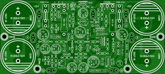
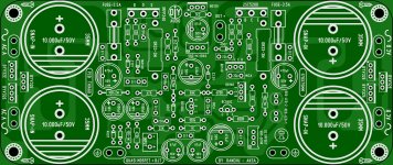
The one on the right is a very nice design from thiagomogi who has posted his artwork in this thread already.
I would suggest that anyone interested in this amplifier build either that PCB or the other one by prasi.
Hi Ranchu32,
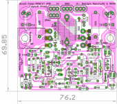
yep, the one by Thiago is more user friendly🙂. Mine is a bit compact😉.
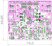
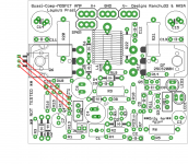
here is a rev4 I had been working on, which is basically the same but with a small U-heatsink option for Q3 based on Terry's testing and some other tweaks (e.g., led option for D7).
reg
Prasi
edit: To e-fortier: A previous Version of this PCB has already been tested by Terry and Thimios. Some values may change after Thimios's "Polishing".
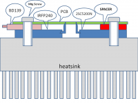
Edit2: Mounting of Q4 on Q6 and also the PCB on heatsink remain the same given in attachments below.
Attachments

Last edited:
Hi Ranchu32,
yep, the one by Thiago is more user friendly🙂. Mine is a bit compact😉.
here is a rev4 I had been working on, which is basically the same but with a small U-heatsink option for Q3 based on Terry's testing and some other tweaks (e.g., led option for D7).
reg
Prasi
edit: To e-fortier: A previous Version of this PCB has already been tested by Terry and Thimios. Some values may change after Thimios's "Polishing".
Edit2: Mounting of Q4 on Q6 and also the PCB on heatsink remain the same given in attachments below.
beautiful PCB Prasi .
Any PCB that make GB is clean ... just choose what you like best .
Best Regards
Hallo Friends.
I have got a e-Mail from kikipcb that the Prasi Boards are shipped to me- should received
here next days, hopefully.
Eric- meanman has also organized GB for Fetzilla Boards, with given green light from Hugh and members, like Ranchu who have worked on this nice Amp.
thiagomogi your idea with integrated capacitors is nice and make it possible to build a
compact case.
I am in to wait actual FetZilla boards and knowing meanman is doing very good service.
I keep you informed here if my boards receives to me.
Cheers Bangla
Hi Prasi
I've been fine tuning and tweaking the past 24 hours to perfect this on 35-42V rails....
C2 = 220p (with the 1n we run the risk of the HPF intruding in the audible band with high Z sources)
R5 = 100k (thanks Terry)
R7 = 680R
R9 = 1k5 /1W
R10 = 68k (I changed my mind after discussion with Hugh)
R12 should be a 600mW part
R15 = 1k2
R19 = 120R (thanks thimios)
R25 should be a 1W part
R23 = 10R
It also be good if you are able to add pads for a ceramic bypass cap around the feedback resistor - R9. More testing is required but if we are going to organise a group buy it would be good to have the option.
Thiago,
Thank you for a wonderful pcb layout!
Could you add two rectifier bridges (one for each supply rail)
at each end of your excellent design?
This would offer a FetZilla-like amp making it very easy
to build without the confusion of configuring power connections.
These cause more problems for DIYers everywhere. After all, AC connections are much easier than DC!
Hugh
Last edited:
Beautiful board thiagnomogi. You can happily remove those 470uF rail decoupling capacitors. When the bulk caps are integrated on board close to the outputs these small caps are not necessary.
Hugh's idea to integrate the bridge rectifiers on board is a very good one. I like these diodes because they have two diodes integrated in the one package (three pins, common cathode) are are relatively inexpensive for the performance.
http://au.rs-online.com/web/p/rectifier-schottky-diodes/8142739/
You only need three packages to make one complete bridge rectifier.
EDIT: on your silkscreen "1k5/1W" should be "1k5-1W" in keeping with the convention used elsewhere.
Last edited:
Thiago,
I would use BYV32E UFSR from Philips. They are inexpensive and one TO220 package has two 10A diodes with both katods connected. See FetZilla layout. A complete bridge has three TO220 packages, very neat and small.
Hugh
Thank your again!
I would use BYV32E UFSR from Philips. They are inexpensive and one TO220 package has two 10A diodes with both katods connected. See FetZilla layout. A complete bridge has three TO220 packages, very neat and small.
Hugh
Thank your again!
Thiago,
I cannot praise your work any higher!
This is some of the best mix of art and engineering that I have ever seen; even prettier than Alex MM's, whose pcbs are legendary.
THANK YOU!
Hugh
I cannot praise your work any higher!
This is some of the best mix of art and engineering that I have ever seen; even prettier than Alex MM's, whose pcbs are legendary.
THANK YOU!
Hugh
Just one more small request.... Can you make the pcb a little wider so those thin tracks going around to the backs of the diodes can are widened a little? As you know, the diodes conduct further only a very short phase angle so the instantaneous charging currents through those traces are very high. With that done this Pcb is finished and I would be honoured if meanman would handle a group buy.
Thank you for your patience , for showing me the direction and encouragement ... could not be better .
AlexMM is still the best , besides Prasi and others, I am still at the beginning
Regards
AlexMM is still the best , besides Prasi and others, I am still at the beginning
Regards
Just one more small request.... Can you make the pcb a little wider so those thin tracks going around to the backs of the diodes can are widened a little? As you know, the diodes conduct further only a very short phase angle so the instantaneous charging currents through those traces are very high. With that done this Pcb is finished and I would be honoured if meanman would handle a group buy.
yes I will.
Thanks Ranchu
PCB looks awesome thiagomogihttp://www.diyaudio.com/forums/members/thiagomogi.html .Waiting for GB ........
Hi Prasi
I've been fine tuning and tweaking the past 24 hours to perfect this on 35-42V rails....
C2 = 220p (with the 1n we run the risk of the HPF intruding in the audible band with high Z sources)
R5 = 100k (thanks Terry)
R7 = 680R
R9 = 1k5 /1W
R10 = 68k (I changed my mind after discussion with Hugh)
R12 should be a 600mW part
R15 = 1k2
R19 = 120R (thanks thimios)
R25 should be a 1W part
R23 = 10R
It also be good if you are able to add pads for a ceramic bypass cap around the feedback resistor - R9. More testing is required but if we are going to organise a group buy it would be good to have the option.
Hi Ranchu,
I have updated the schematic and layout to reflect current values and add-on components (C16), I have named it rev 4.1 as reference schematic.
reg
Prasi
Attachments

- Home
- Amplifiers
- Solid State
- Very simple quasi complimentary MOSFET amplifier