Thimios,
I am sorry I have not tried LTSpice but I will do it first thing tomorrow... today I was preoccupied with the preparations for the new product in the Aspen lineup!
Hugh
I am sorry I have not tried LTSpice but I will do it first thing tomorrow... today I was preoccupied with the preparations for the new product in the Aspen lineup!
Hugh
Thimios,
I am sorry I have not tried LTSpice but I will do it first thing tomorrow... today I was preoccupied with the preparations for the new product in the Aspen lineup!
Hugh
Don't worry take your time,i'm out for a few days.
Last edited:
Hi , i posted a comment and you recomanded me to build the first schematic at post no1
this one:
Mooly said : Q3 actually needs to be an NPN
kasey197: " two initial comments:
biasing for Q5 looks dodgy - missing a resistor i think.
Q3 needs to be fed from junction of Q1 and R5 - looks like a typo. "
so i need to change q3 to be npn and it works ?
Thanks
this one:
Mooly said : Q3 actually needs to be an NPN
kasey197: " two initial comments:
biasing for Q5 looks dodgy - missing a resistor i think.
Q3 needs to be fed from junction of Q1 and R5 - looks like a typo. "
so i need to change q3 to be npn and it works ?
Thanks
Ranchu LTSpice Analysis
Hi Folks,
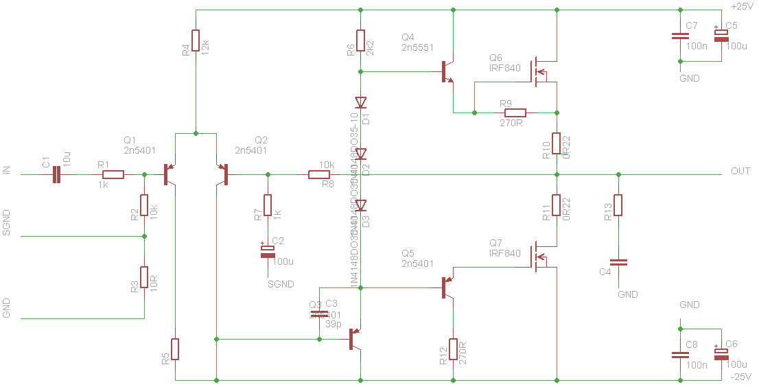
I have put the Ranchu QUASI through LTSpice, and some of the findings are in the schematic attached.
A few issues:
1. Gain is modified by R5 68k and is 22.1, which is 26.9dB.
2. On the schemat I have deleted the input offset network for simplicity, which would normally be on the real circuit as shown on Ranchu's schemat. I have inserted the offset into the source heading.
3. I have tagged a few actual (simulated) values to give some idea of current and voltage in critical areas around the circuit. They have 7 sig figs, which is of course the ideal. In reality it won't be measured that well and there will be variations due to component imperfects and tolerances.
4. I have kept lag comp as C4 (33pF) but added the feedback shunt C11 (68pF) while dropping the bypass across R5 68k. I have added a Miller cap across base/collector on Q5, the phase inverter. All this flattens the gain structure (it was toppy, dangerous for stability and ringing) and ensures the net gain is below unit at the frequency where phase shift is 180 degrees (where the negative feedback turns nasty into positive feedback, creating a destructive oscillator).
5. These tiny pF caps used in compensation are very difficult to predict with math and simulators. The badly affect the sound quality too, so the best option is to try it on a real amp and have a listen. If you have done it a few times, you develop a sense of under comp, or over comp. Once you are ready, you try it with a few caps across an 8R resistor load. The most difficult combination if 100nF//8R.
6. Notwithstanding, I do not say this is the correct combination of compensation caps. It's a start, there are no definitive answers unless you actually DO it.
7. This amp has very good harmonic profile. H2 is high at 12.5W into 8R; it's at -70dB, and H4 is around -84dB. H5 is well below -100dB, which is very good - no machine tones, very warmish and engaging. Recommended.
Thimios, I hope this helps, and directs your efforts to polish this lovely little amplifier! Thank you for your hard work, I'm just the remote fanatic!
Cheers,
Hugh
Hi Folks,
I have put the Ranchu QUASI through LTSpice, and some of the findings are in the schematic attached.
A few issues:
1. Gain is modified by R5 68k and is 22.1, which is 26.9dB.
2. On the schemat I have deleted the input offset network for simplicity, which would normally be on the real circuit as shown on Ranchu's schemat. I have inserted the offset into the source heading.
3. I have tagged a few actual (simulated) values to give some idea of current and voltage in critical areas around the circuit. They have 7 sig figs, which is of course the ideal. In reality it won't be measured that well and there will be variations due to component imperfects and tolerances.
4. I have kept lag comp as C4 (33pF) but added the feedback shunt C11 (68pF) while dropping the bypass across R5 68k. I have added a Miller cap across base/collector on Q5, the phase inverter. All this flattens the gain structure (it was toppy, dangerous for stability and ringing) and ensures the net gain is below unit at the frequency where phase shift is 180 degrees (where the negative feedback turns nasty into positive feedback, creating a destructive oscillator).
5. These tiny pF caps used in compensation are very difficult to predict with math and simulators. The badly affect the sound quality too, so the best option is to try it on a real amp and have a listen. If you have done it a few times, you develop a sense of under comp, or over comp. Once you are ready, you try it with a few caps across an 8R resistor load. The most difficult combination if 100nF//8R.
6. Notwithstanding, I do not say this is the correct combination of compensation caps. It's a start, there are no definitive answers unless you actually DO it.
7. This amp has very good harmonic profile. H2 is high at 12.5W into 8R; it's at -70dB, and H4 is around -84dB. H5 is well below -100dB, which is very good - no machine tones, very warmish and engaging. Recommended.
Thimios, I hope this helps, and directs your efforts to polish this lovely little amplifier! Thank you for your hard work, I'm just the remote fanatic!
Cheers,
Hugh
Attachments
Thank you , but why does it use a mosfet and a bjt ? and not two mosfets ?
Hi Bruno,
You should glance over from the beginning of the thread, to understand some of the design goals of this amp.
reg
Prasi
Bruno,
A few good reasons:
1. Better harmonic profile.
2. Higher output from the design rail voltage.
3. Cheap build, good npn and nmos are inexpensive.
4. Non-conformism. People think it will never work, but it's fabulous.
5. Hybrids rule!!
Hugh
A few good reasons:
1. Better harmonic profile.
2. Higher output from the design rail voltage.
3. Cheap build, good npn and nmos are inexpensive.
4. Non-conformism. People think it will never work, but it's fabulous.
5. Hybrids rule!!
Hugh
Bruno,
A few good reasons:
1. Better harmonic profile.
2. Higher output from the design rail voltage.
3. Cheap build, good npn and nmos are inexpensive.
4. Non-conformism. People think it will never work, but it's fabulous.
5. Hybrids rule!!
Hugh
Very interesting thread, I just find non-conformism amp fascinating !!
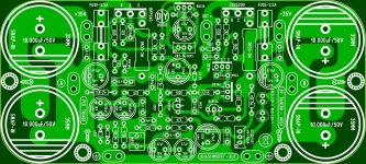
I hope a GB for the PCB shown on post 477 will soon be created, or has it been done already and I'm late to the party...lol
Thiagomogi did an amazing job with his pcb design.
BR,
Eric
Last edited:
Hi Eric
No group buy planned yet, but I believe at least one forum member has ordered some boards from a board house and may have some spares for sale soon.
The design posted by Hugh at #477 is for the Fetzilla, a different project, but I agree that this layout is very nice indeed!
No group buy planned yet, but I believe at least one forum member has ordered some boards from a board house and may have some spares for sale soon.
The design posted by Hugh at #477 is for the Fetzilla, a different project, but I agree that this layout is very nice indeed!
Hi Eric
No group buy planned yet, but I believe at least one forum member has ordered some boards from a board house and may have some spares for sale soon.
The design posted by Hugh at #477 is for the Fetzilla, a different project, but I agree that this layout is very nice indeed!
I'm more than happy to organize a groupsbuy if you want me too😎
Hi Eric
No group buy planned yet, but I believe at least one forum member has ordered some boards from a board house and may have some spares for sale soon.
The design posted by Hugh at #477 is for the Fetzilla, a different project, but I agree that this layout is very nice indeed!
Hi Ranchu,
Post 477 shows 2 different PCB, have a look at the right one.
This design seems to be from you and Hugh (written on the PCB), do you authorise someone to go aheah and order PCBs ?
Thanks,
Eric
The one on the right is a very nice design from thiagomogi who has posted his artwork in this thread already.
I would suggest that anyone interested in this amplifier build either that PCB or the other one by prasi.
I would suggest that anyone interested in this amplifier build either that PCB or the other one by prasi.
Yes, of course! This is open source as I understand.
I am considering building one myself just to compare with my amps. Who knows this quasi might embarass them and it does I will have to change my product lineup!
Hugh
I am considering building one myself just to compare with my amps. Who knows this quasi might embarass them and it does I will have to change my product lineup!
Hugh
Last edited:
Meanman1964,
Looks like you've got the green light for a GB. Thanks for sharing AKSA and Ranchu32.
Were both PCB from Thiagomogi and Prasi fully tested and fine tuned or are they at their Beta stage ?
Sorry for all the questions, I haven't read the 56 pages of the thread.
BR,
Eric
Looks like you've got the green light for a GB. Thanks for sharing AKSA and Ranchu32.
Were both PCB from Thiagomogi and Prasi fully tested and fine tuned or are they at their Beta stage ?
Sorry for all the questions, I haven't read the 56 pages of the thread.
BR,
Eric
- Home
- Amplifiers
- Solid State
- Very simple quasi complimentary MOSFET amplifier