Ranchu QUASI Design
Hi Sam,
I thought DACZ did a great job on this! Let us assume that Q5 and the two output devices, Q6 and Q7 are all on a heatsink, and that Q4 the Vbe multiplier should be thermally mounted to either Q6 or Q7.
All the pinouts look terrific too, one of the nicest schemats I have ever seen!
Cheers,
Hugh
Attachments
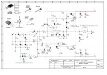
I would use this schematic as-is on 25V rails.
You might reduce the VAS bootstrap resistors, R12 and R15 to, say, 1k8 and 1k2, respectively, in order to bring the standing current back up a little, but that is of relatively minor concern.
I think somewhere along the line the input transistor (Q1) was changed from a KSA992 to a 2N5401. It doesn't really matter which device you use, so long as you recognise that the pinouts are different. I would choose whatever device the board you are using has been designed for.
I guess my only quibble is that the VAS bootstrap cap (C6) is a little too small for good LF distortion, particularly if you reduce the bootstrap resistors as suggested above. You really don't need a 63V part if you are running 25V rails, so my advice is to substitute the biggest 35V that will fit on the board - but no more than 470uF.
You really should make every effort to source the A1381 for Q3.
Hugh, what you are saying is true. My point is that as per the PCB layout in post 1231, Q3 is on the common heatsink, while Q5 is not on any heatsink. Whereas the schematic diagram shows the opposite.
Question is whether Q5 (Phase Inverter) or Q3 (Vas Buffer), or both should be on the heatsink?
Question is whether Q5 (Phase Inverter) or Q3 (Vas Buffer), or both should be on the heatsink?
With 42V rails Q3 should be mounted on its own small heatsink. At lesser voltages this is not required. The phase inverter does not require heat sinking.
Hi Sam,
At 42V rails, the dissipation on the Q3 KSA1381 (the buffer) is 395mW and Q5 KSA1381 (the inverter) is 243mW at idle and probably less even in full output.
This is thermally fine for a TO126 sitting alone on a pcb with good ventilation but no heatsinks. You could use a small flag heatsink (32C/watt) for Q3, but not for Q5. This would have been identified if there had been a problem; the entire active chain was considered when during LTSpice analysis was done and then by Ranchu when he used his Quasi in a sub-tropical city, Brisbane, where any thermal issues would be been clearly evident months back.
So, be assured, this is a highly evolved, refined, tested design and both Q3 and Q5 may be left free standing, with no heatsinking.
I commend this amp to you. The sound is very good, almost tubey; the harmonic profile is very musical.
At any rail less than 42V the thermal issues relax even more. You can be sure!
Cheers,
Hugh
Good to know it should work as is on 25v rails. I will try it out and see how it sounds. I now have several bags of KSA1381 (great transistor so don't want to run out again). Wondering if I should swap out the MJE350's that is currently there?
First step is to listen - probably still sounds great. Then if it ain't broke I am not going to fix it 🙂
Could a 100VA transformer be enough at 25v rails? (18vac) I am looking to make a very compact case for this setup. Actually dual 100VA toroidal are not expensive at all and will improve soundstage. But still wondering if a single 100VA can work for this setup.
http://www.antekinc.com/as-1218-100va-18v-transformer/
Last edited:
I would use this schematic as-is on 25V rails.
You might reduce the VAS bootstrap resistors, R12 and R15 to, say, 1k8 and 1k2, respectively, in order to bring the standing current back up a little, but that is of relatively minor concern.
I think somewhere along the line the input transistor (Q1) was changed from a KSA992 to a 2N5401. It doesn't really matter which device you use, so long as you recognise that the pinouts are different. I would choose whatever device the board you are using has been designed for.
I guess my only quibble is that the VAS bootstrap cap (C6) is a little too small for good LF distortion, particularly if you reduce the bootstrap resistors as suggested above. You really don't need a 63V part if you are running 25V rails, so my advice is to substitute the biggest 35V that will fit on the board - but no more than 470uF.
You really should make every effort to source the A1381 for Q3.
Thank you very much Ranchu

Good to know it should work as is on 25v rails. I will try it out and see how it sounds. I now have several bags of KSA1381 (great transistor so don't want to run out again). Wondering if I should swap out the MJE350's that is currently there?
First step is to listen - probably still sounds great. Then if it ain't broke I am not going to fix it 🙂
Could a 100VA transformer be enough at 25v rails? (18vac) I am looking to make a very compact case for this setup. Actually dual 100VA toroidal are not expensive at all and will improve soundstage. But still wondering if a single 100VA can work for this setup.
AS-1218 - 100VA 18V Transformer - AnTek Products Corp
Hi X,
To save some room in a compact case maybe you could use one of these, I made some test with my VSSA and it sounded good. I believe Terry had some good results also. This is the PSU I had in mind 😉
110V 220V 200W Digital Amplifier Power Supply Board with Switching | eBay
p.s. I don't know the seller, this is just to show the smps. At that price, get 1 per channel.
BR,
Eric
Eric,
Thanks for the tip. Looks nice. What is ripple under say 200mA load? Good that it has 15v aux rails for a preamp.
Thanks for the tip. Looks nice. What is ripple under say 200mA load? Good that it has 15v aux rails for a preamp.
Very nice work Dacz.
I would add some note on p.2 of your schematic ; Q4 should be thermally coupled to Q6 and Q3 only requires a small heatsink but doesn't need to be thermally coupled to Q6 or the main heatsink.
BR,
Eric
I would add some note on p.2 of your schematic ; Q4 should be thermally coupled to Q6 and Q3 only requires a small heatsink but doesn't need to be thermally coupled to Q6 or the main heatsink.
BR,
Eric
Very nice work Dacz.
I would add some note on p.2 of your schematic ; Q4 should be thermally coupled to Q6 and Q3 only requires a small heatsink but doesn't need to be thermally coupled to Q6 or the main heatsink.
BR,
Eric
thanks Eric.. in my opinion there is no side effect if Q3 is mounted on main heatsink... save space and a penny for small heatsink 😀
regards,
dacz
Ah a nice tip Eric- i will keep an eye to that supply, because with build in
we can have a mighty POWER midget case. 😀.
I've done it to watch list.
Like Dacz i will also mount Q3 on main heat sink. With TO126 for distances it
gives me trouble to face the OP transistors in parallel in line- used a different
way.
we can have a mighty POWER midget case. 😀.
I've done it to watch list.
Like Dacz i will also mount Q3 on main heat sink. With TO126 for distances it
gives me trouble to face the OP transistors in parallel in line- used a different
way.
thanks Eric.. in my opinion there is no side effect if Q3 is mounted on main heatsink... save space and a penny for small heatsink 😀
regards,
dacz
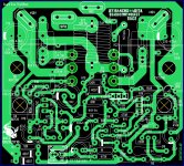
I think I just got it, in your PCB layout from post 1231, are Q3 and Q4 located under the PCB like the output transistors ?
Thanks,
Eric
dacz,i think mounting holes (for horizontal transistors ) are missing in your layout in post #1231. pl take a look. for to-126, they need to be big enough so that screw head can also pass through the hole.thanks Eric.. in my opinion there is no side effect if Q3 is mounted on main heatsink... save space and a penny for small heatsink 😀
regards,
dacz
reg
prasi
Last edited:
here it is.. guess all ok now
Q4 can be mounted direct to heatsink or coupled to Q6 and use the mounting hole of Q4 for the wiring. Q3 can be mounted also direct to heatsink or free standing on PCB and provide a separate clip-on heatsink.
Q4 can be mounted direct to heatsink or coupled to Q6 and use the mounting hole of Q4 for the wiring. Q3 can be mounted also direct to heatsink or free standing on PCB and provide a separate clip-on heatsink.
Attachments
Last edited:
Great work Dacz.
The zipped file is a xyz.lay6, what is it ?
BR,
Eric
Eric its the sprint file with which the layout was created and from which people can export Gerber's or print DIY PDF files.
- Home
- Amplifiers
- Solid State
- Very simple quasi complimentary MOSFET amplifier