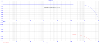
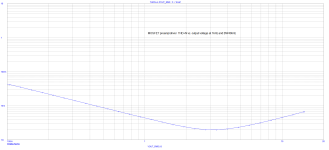
I built this circuit back in the year 2002 and I used it as a driving stage for my class A power buffer PM-A1 (gain 1x, 30W/8ohm). It was working very well with quite good parameters, as can be seen below.

(D1 is a Zener diode 6V8)


I am showing above the THD+N plot (1kHz, BW40kHz) to include noise part as well. This is often omitted, unfortunately.
Loopgain stability is perfect, with 87° phase margin.
(D1 is a Zener diode 6V8)


I am showing above the THD+N plot (1kHz, BW40kHz) to include noise part as well. This is often omitted, unfortunately.
Loopgain stability is perfect, with 87° phase margin.
Last edited:
Yes, it was originally built with IRF9610.
Why MOSFETs? EMI immunity.
Some historical measurements and photos below.


(this version is with OPA445 as a driver)
Why MOSFETs? EMI immunity.
Some historical measurements and photos below.
(this version is with OPA445 as a driver)
Hi, PMA!
Why do you actively drive base of Q1 with Q2 (tracking idle current of R12) while more sensitive to common mode error M3 was kept without Early effect compensation?
If you replace R15 and R9 with RCR-networks - this will provide you with effective soft-start.
Why do you actively drive base of Q1 with Q2 (tracking idle current of R12) while more sensitive to common mode error M3 was kept without Early effect compensation?
If you replace R15 and R9 with RCR-networks - this will provide you with effective soft-start.
Yes, Zener.D1 a zener?
To provide M3 gate around 4,5 Volts with desirable voltage drop at idle current to R6.Value?
It will be better if passive Zener reference will be changed to the active Vbe tracking of R6 voltage drop and accordingly drive an M3 gate.
D1 was a Zener diode 6V8. Post #1 edited.
This circuit was a very old one, posted here rather for fun. As I already wrote, it was built in 2002. A closed chapter, without any intentions to make "improvements". However, it worked very well.
Maybe the power buffer was more interesting 😉. It was placed outside the FB loop. Iq = 1.5A.

This circuit was a very old one, posted here rather for fun. As I already wrote, it was built in 2002. A closed chapter, without any intentions to make "improvements". However, it worked very well.
Maybe the power buffer was more interesting 😉. It was placed outside the FB loop. Iq = 1.5A.
The IRF9630 has a worst case +/-1V variation in threshold voltage according to the datasheet - that doesn't bode well for the amplifier output offset voltage. Even if you match them MOSFET threshold voltages change with age due to ion migration in the gate, and with temperature.
- Home
- Source & Line
- Analog Line Level
- Very simple MOSFET preamp/driver