thimios
You are right BJTs and Verticals are way better down bellow 100Hz.
Some say crazy people are making crazy things - like putting the vacuum tube not at the front of the amp but on the back 😀
I got some nice advice of a very wise member of this forum and I have prepared another hybrid amplifier - prototype so far.
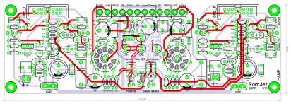
Solid state amplifier got a current driven SRPP NFB processor. Before signal goes to the inverting input it is processed with vacuum tube.
Some will say that tube is placed at the wrong side of the amplifier 😀
The special circuit is developed to smoothly switch in between standard solid state amplifier and vacuum tube processed NFB.
The only thing is that so far I do not know if it works. looking forward to find out.
Regards
You are right BJTs and Verticals are way better down bellow 100Hz.
Some say crazy people are making crazy things - like putting the vacuum tube not at the front of the amp but on the back 😀
I got some nice advice of a very wise member of this forum and I have prepared another hybrid amplifier - prototype so far.
Solid state amplifier got a current driven SRPP NFB processor. Before signal goes to the inverting input it is processed with vacuum tube.
Some will say that tube is placed at the wrong side of the amplifier 😀
The special circuit is developed to smoothly switch in between standard solid state amplifier and vacuum tube processed NFB.
The only thing is that so far I do not know if it works. looking forward to find out.
Regards
Attachments
AKSA
I have ordered PCBs for the prototype, have no time to eatch the board.
What I have testet is 20x gain tube preamp + 2x gain solid state amplifier, the resaults are stunning (for me anyway), hope the NFB tube will be good too.
The worst thing is that I have another idea. Just look bellow
ECC832 JJ - Lampy Elektronowe On-Line. Największy polski sklep z technik
ECC832 --> double triode, ECC83 and ECC82 , my idea is to prepare a small preamp:
-ECC83 as input triode
-ECC82 + mosfet CCS as SRPP
-NFB wired up to the ECC83 cathode
The both cathodes will be referenced close to the GND so there will be no need to elevate the heater.
Kay Pirinha
Schematic will be ready when I receive the boards and solder them together. For now I do not know if it will work OK.
Regards
Last edited:
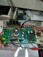
A step farther.
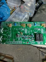
Testing the protection circuit.
Power on
Delay relay click.
Temperature alarm.
Attachments

Last edited:
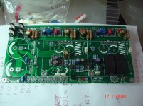
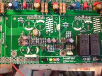
I-amp+VSHA IPS
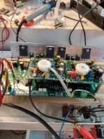
Second chanel on the road.
Second chanel on the road.
Attachments
Last edited:
Thanks Hugh,i hope that i will be in situation to answer soon.🙂Nice work, Thimios......
How does it sound?
Hugh
The second chanel is close to complete and then i will listen to it.
I can't hide that listening to the IPS in co - operation with Valery's N.S OPS,i have very good impressions!
I like the way that bass are presents even at the low volume setting.
The same using Ostiper Slewmaster as OPS.
Now VSHA is located at his home.😉
Let's wait to see how this can feel.😎
PS Please keep in mind that this is a test bed and not the final housing.
Last edited:
thimios
I see You found the time to solder the simple main board, looks good 😀
On the left side of the input board there is a small jumper for the signal GND which is going through left metal spacer fitting.
Regards
I see You found the time to solder the simple main board, looks good 😀
On the left side of the input board there is a small jumper for the signal GND which is going through left metal spacer fitting.
Regards
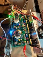
First attempt to stereo!
An externally hosted image should be here but it was not working when we last tested it.
Attachments
Awesome!
Is this circuit different than the boards I sold a while back when we were having that big sale on Slewmaster IPS boards?
Is this circuit different than the boards I sold a while back when we were having that big sale on Slewmaster IPS boards?
Awesome!
Is this circuit different than the boards I sold a while back when we were having that big sale on Slewmaster IPS boards?
Hi Terry look here.VSHA ECC82 - iAMP - DIY way to build Your own amplifier
My valve bases not fit well on the board.
Can you tell me what type of base used for perfectly fit.
As my second valve is a used 12au7A and not in good condition i must go for two new ecc88 when i will have the money.
Can you tell me what type of base used for perfectly fit.
As my second valve is a used 12au7A and not in good condition i must go for two new ecc88 when i will have the money.
Last edited:
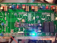
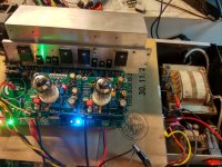
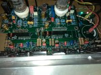
A more complete configuration
+/-43v
Two new 12au7 Electro Harmonics tubes.
+/-43v
Two new 12au7 Electro Harmonics tubes.
Attachments
Last edited:
- Home
- Amplifiers
- Solid State
- Very Simple Hybrid Ampifier