platon
Nice army, I am not familiar with tube world a lot, tell me please if the Siemens I received today are any good ??
I am going to do some further development with ecc88 based amp and I need some decent tubes.
Thanks
Yes, the Siemens is good.
Sajti
Hmmmm.... I guess, that Siemens is good, but Amperex is better. Anyway the Amperex 6DJ8 is overpriced as a hell. I found them between 40 and 100USD.
Sajti
platon
Thanks.
I have putted into the socket above siemens tube, performs superb, no issues at all with stability.
OS mentioned to change a compensation a bit, later on I will try to make some tests.
Bellow ECC88 in the circuit.
Thanks.
I have putted into the socket above siemens tube, performs superb, no issues at all with stability.
OS mentioned to change a compensation a bit, later on I will try to make some tests.
Bellow ECC88 in the circuit.
Attachments
platon
Thanks.
I have putted into the socket above siemens tube, performs superb, no issues at all with stability.
OS mentioned to change a compensation a bit, later on I will try to make some tests.
Bellow ECC88 in the circuit.
What is the bias current for the ECC88?
Thanks:Sajti
The bias current is 4,4mA total (2,2mA per one triode). Is that OK ?
The grid is seted at -1V, I can easly set it for -1,2V with a bit higher bias.
The grid is seted at -1V, I can easly set it for -1,2V with a bit higher bias.
The bias current is 4,4mA total (2,2mA per one triode). Is that OK ?
The grid is seted at -1V, I can easly set it for -1,2V with a bit higher bias.
Looks good for first seen. What are the value of the anode resistors?
Sajti
On the anode resistors there is around 47V at the moment.
They are 22kohm, aren't they? It looks a bit much for me. There are very low amount of voltage remains on the tube.
Sajti
They are 22kR for ecc82. With ecc88 the anode resistors are 4,7kR
OK. Where did You measured the 47V exactly?
Sajti
47V were measured at the anode resistor (anode voltage).
4700R * 0,0022A = 10,34V voltage drop on anode resistors.
58V is my supply - 10,34 = 47V
Is that fine ?
4700R * 0,0022A = 10,34V voltage drop on anode resistors.
58V is my supply - 10,34 = 47V
Is that fine ?
You know, since the voltage here is very small, the tube is used only to produce small variations in current. 47V at Vak of a 12AU7 is just fine; thank you for the information, Peter, very good circuit.
The rp of a 12AU7 is 6,500, but at this very low current of 2.2mA it could be 10K. A 4k7 anode is very stiff for a tube with this rp, and it will distort with highish voltage change. Here there is very little voltage change, since it's related only to the error signal from the LTP.
If Terry thinks it's a lovely sound, that's enough for me. He's heard just about everything.
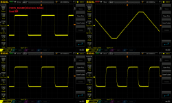
May I ask something? Can you do an oscillograph of the voltage wrt ground at the anode for a 1Vp input at 1KHz?
Ciao,
Hugh
The rp of a 12AU7 is 6,500, but at this very low current of 2.2mA it could be 10K. A 4k7 anode is very stiff for a tube with this rp, and it will distort with highish voltage change. Here there is very little voltage change, since it's related only to the error signal from the LTP.
If Terry thinks it's a lovely sound, that's enough for me. He's heard just about everything.
May I ask something? Can you do an oscillograph of the voltage wrt ground at the anode for a 1Vp input at 1KHz?
Ciao,
Hugh
Low first stage current is the very reason for this type circuit.
Sansui and other Japanese variants of this circuit averaged about 1ma
per device (Jfet).
Another "trick" you can play with this topology is to run the first stage
from a much lower regulated supply. I suppose, this would only apply to Jfet's.
OS
Sansui and other Japanese variants of this circuit averaged about 1ma
per device (Jfet).
Another "trick" you can play with this topology is to run the first stage
from a much lower regulated supply. I suppose, this would only apply to Jfet's.
OS
AKSA
The bellow values are for ecc88 tube:
4.7kR - anode load resistor
2.2mA bias per single triode
47V - anode voltage.
The values for 12AU7 are bit differend:
22kR - anode load resistor
800uA - bias per single triode
I will do the anode voltage measurement tomorrow but with ecc88 tube.
OS
That is why I have added second LTP (transistor one) for comfort of setting the tube bias (various anode voltages) - just turn the pot and nothing else have to be adjusted.
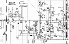
I do not know if have you seen one of Denons I think, the two front LTP's are folded (frond one is running from lower voltage zener supply=V+ rail and second LTP i running from full V- rail), If Ill find schematic I will post it.
EDIT:
Sorry it was yamaha 1020, my favourite one, briliand amplifier.
The bellow values are for ecc88 tube:
4.7kR - anode load resistor
2.2mA bias per single triode
47V - anode voltage.
The values for 12AU7 are bit differend:
22kR - anode load resistor
800uA - bias per single triode
I will do the anode voltage measurement tomorrow but with ecc88 tube.
OS
That is why I have added second LTP (transistor one) for comfort of setting the tube bias (various anode voltages) - just turn the pot and nothing else have to be adjusted.
I do not know if have you seen one of Denons I think, the two front LTP's are folded (frond one is running from lower voltage zener supply=V+ rail and second LTP i running from full V- rail), If Ill find schematic I will post it.
EDIT:
Sorry it was yamaha 1020, my favourite one, briliand amplifier.
Attachments
Last edited:
OS
That is why I have added second LTP (transistor one) for comfort of setting the tube bias (various anode voltages) - just turn the pot and nothing else have to be adjusted.
I do not know if have you seen one of Denons I think, the two front LTP's are folded (frond one is running from lower voltage zener supply=V+ rail and second LTP i running from full V- rail), If Ill find schematic I will post it.
EDIT:
Sorry it was yamaha 1020, my favourite one, briliand amplifier.
Notice they all use the lead/lag comp. Some take it from the final output,
some from the Vas. This depends on where the OP pole falls (speed).
It helps to stabilize the IPS with gain changes. I noticed a much better
tolerance of device swapping with this in place ... why I mentioned it.
The Valve is like a Jfet that "ages".(they don't do that) 😀
OS

OS
In Spice I had to putt large 47pF cap across the NFB resitor to keep it stable with RC networ atatched to front stage.
Please take a look if it makes any sese.
Thanks
Much less , like 5-15p. 47 would bring the unity gain xover down to 150k.
600-800K is normal for this amp.
I use both OPS 5p back to nfb and Vas 8.2p to nfb - 2 leads.
The tube may differ.
You would have to scope square wave response while adjusting either
value.
Even the R/C at input diff. would be different for the tube. I only
have fet/bjt experience. 😱
PS - these 3 compensations "voice" this amp. You can can "mold" the phase/gain relationship.
much more than a LIN/CFA.
OS
Last edited:
- Home
- Amplifiers
- Solid State
- Very Simple Hybrid Ampifier