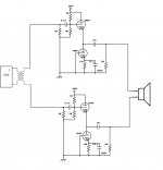
perhaps the attached will give clearer idea what I was trying to convey with that schematic, how the 2 amps would be connected for balanced drive.
and what the result would be if the 0.1uf input caps (and preceding 1M resistor) were removed.
and what the result would be if the 0.1uf input caps (and preceding 1M resistor) were removed.
Attachments
Last edited:
What's the point in balanced drive?
It is "bridged", actually. Used when the amp can not output enough voltage swing due to limitations of a battery voltage. Twice higher voltage, with the same load impedance output current of each half-amp is twice higher, so output power is 4 times higher.
It is "bridged", actually. Used when the amp can not output enough voltage swing due to limitations of a battery voltage. Twice higher voltage, with the same load impedance output current of each half-amp is twice higher, so output power is 4 times higher.
That topology also doubles output impedance, which isn't helpful for what you're doing. You're also best off with some feedback to set gain and keep things working more identically between halves. A differential first stage would probably do OK at this too.
The point as you say is 4 times the power, or realistically 2 times the power with the same headphones. also making it possible to omit output caps by balancing voltage on the output evenly.
Most importantly my experience using 2 different SE SS amps in bridged configurations was that they sounded a lot better.
In one of these cases the SE SS amp was based paralleling op amps to increase output current. To bridge this amp I halved the op amps per channel instead of doubling them, so power output did not really increase but this implementation still sounded far better bridged, example, the OPA1622 used were running on 17V supply.
With high impedance HPs the tubes would still be dealing with reasonable loads when bridged I think, but still the output impedance is a bigger obstacle with OTL than the SS amps.
I am not sure, only that polypropylene output caps would be about the same cost (or even more) as some resistors and a couple more tubes, which could run off the same power supply.
I can see that there isnt much point doing this as the result will most likely be disappointing, im mostly concerned about lack of power. It would make more sense to stay single ended and add the extra tubes in parallel, eliminating output caps is more of a novelty compared to lowering output impedance. Also it would need some kind of DC protection and then things become over-complicated.
For output caps, instead of some boutique caps these KEMET DC Link are probably nearly as good (still far better than any electrolytic) and very good value. I used these before in a power supply and notice they have pure copper leads instead of copper clad steel like a lot of general purpose polypropylene caps
For output caps, instead of some boutique caps these KEMET DC Link are probably nearly as good (still far better than any electrolytic) and very good value. I used these before in a power supply and notice they have pure copper leads instead of copper clad steel like a lot of general purpose polypropylene caps
Last edited:
The point as you say is 4 times the power, or realistically 2 times the power with the same headphones. also making it possible to omit output caps ....
With tubes into low-Z loads, we are often *current* limited. Then the bridge-mode power is the *same*.
What we'd usually turn to is Parallel mode.
Yes, paralleling does not semi-cancel 2nd distortion. And does not eliminate output caps, though _I_ would be very dubious about any two tubes matching close-enough not to damage headphones (especially at turn-on/turn-of).
thanks for clarifying, 40mA does seem awfully low if that measured the same as an op amps output current. The op amps in a DAC's unbalancing circuit will swing at least 50mA, though not in class A and not solely as a buffer. The transparency of OTL is the most appealing thing but without power thats not worth much.
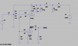
Gain is roughly 1/2 of the mu of the first tube.
The circuit can run without gain with the addition of fixed biasing... This unfortunately adds a cap.
See attached.
Add a grid stopper if you want, but I've never needed it with this circuit. Also assume the same 620R/47u filter (which was based on an SMPS, and because I had the parts already. If you use a passive power supply, use 220uF instead.
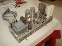
Its been a while but im finally getting around to putting this amp/buffer together...
This design is white cathode follower I think.
You get both lower output impedance and higher output current with this configuration, its what the schitt valhalla 2 employs and that is known to be one of the more neutral and ''SS-like'' tube amps you can buy.
Power supply will be linear using 115 x 2 transformer... The tricky part is managing supply voltage, I will either need HV regs to burn off nearly 50VDC at 230VAC or run tubes at lower voltage with basic cap multiplier at 115VAC.
I assume higher voltage is best for SQ, output current headroom decreases as voltage goes down, are there more reasons for running higher voltages?
Tubes could be run at 300V limit, would nearly half dissipation in regs and could bring further sound improvement with same idle current. tube life could suffer but 6n6p are dead cheap and I have 8 pairs to test longevity.
I have a 6VAC trafo for the heaters so the option for DC or AC heater supply is there, AC seems preferable to me but the possibility of hum is even greater with headphones... or maybe not with no gain. Not hard to test both 🙂
Last edited:
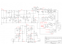
It's actually based on an Aikido. It's SE but you can modify it to be push pull.
It should draw about 23mA / channel do you could always just increase the RC filter resistor. You want lower voltage to get the drive current but keep within Pd.
Here's more info. Aikido Push-Pull
It should draw about 23mA / channel do you could always just increase the RC filter resistor. You want lower voltage to get the drive current but keep within Pd.
Here's more info. Aikido Push-Pull
Oh so it is, i thought you had wrote something about each tube swinging 20mA but must be confusing with a tube cad article.
its seems like PP version has most of the same benefits of SE version, is there some disadvantage im not seeing?
So aikido main advantage is PSRR
I planned to use cap multiplier or salas regulator for a low impedance, low ripple supply, I really hated the sound of RC filters powering SS amps and more importantly I'm aiming to test the sound differences between a transistor and tube buffer under the closest conditions possible.
Do you know of any designs that trade the PSRR of aikido for something else i.e less distortion or output z?
The PP version will swing 40mA 🙂
The Aikido-ing is removed in my version. It has good PSRR because it's actively loaded unless I'm wrong. I've never used a linear supply to power it. The fact that I'm running mine on an SMPS for heaters that also powers the boost converter and I hear no PS noise, hiss, or hash is great, but I don't expect any hum this way. In the push pull version, the "aikido-ing" is what makes it swing both ways.
The Aikido-ing is removed in my version. It has good PSRR because it's actively loaded unless I'm wrong. I've never used a linear supply to power it. The fact that I'm running mine on an SMPS for heaters that also powers the boost converter and I hear no PS noise, hiss, or hash is great, but I don't expect any hum this way. In the push pull version, the "aikido-ing" is what makes it swing both ways.
The tube cad aikido can be reduced to aikido cathode follower and remain an ''aikido''.
The physical difference between the tube cad ACF and WCF circuits I can see is top triode plate resistor that allows WCF to work in push pull, increasing output current, lowers distortion and also decreases output impedance.
The ACF has ''low'' output impedance but I realised it's a relative statement, a simple CF has even lower output impedance but neither are particularly low in the context of headphone, only line level.
WCF is half that of the CF which is big step in the right direction for headphone.
Also maybe the push-pull WCF would not sound as good as SE into a high z input when output z doesnt matter as much.
Your buffer connects lower triode grid to ground, not b+ like aikido which seems to be the trick to its high PSRR. really its quite different to any of tube cad CF variations
was it only the first version with gain that is ''aikido'' or just that the design is based on it but not really aikido?
Last edited:
~~
This is the amp I ended up building, a WCF and it sounds far better than expected.
I tested with and without cathode bypass cap but felt the cap really messes with the sound (hashy, gritty), 470uf were used.
May try bypassing 46r grid stoppers completely.
Dual 160V supply from 115V+115V trafo,
That CRCRC filter is enough for dead silent operation with 300ohm sennheiser.
Very affordable and great sounding PP cap for the output: C4AQCBW5750A3NJ KEMET | Mouser Ireland
I had 40uf on hand but would prefer to use a bit higher
Attachments
Last edited:
This is the amp I ended up building, a WCF and it sounds far better than expected.
I tested with and without cathode bypass cap but felt the cap really messes with the sound (hashy, gritty), 470uf were used.
May try bypassing 46r grid stoppers completely.
Dual 160V supply from 115V+115V trafo,
That CRCRC filter is enough for dead silent operation with 300ohm sennheiser.
Very affordable and great sounding PP cap for the output: C4AQCBW5750A3NJ KEMET | Mouser Ireland
I had 40uf on hand but would prefer to use a bit higher
laserscrape:
I would very much appreciate it if you are will to publish the LTspice listing inclusive the model of the used tube!
laserscrape:
I would very much appreciate it if you are will to publish the LTspice listing inclusive the model of the used tube!
I can publish it if you like but there was no real 6n6p model if thats what you mean, its just generic triode symbol labeled 6n6p
I can publish it if you like but there was no real 6n6p model if thats what you mean, its just generic triode symbol labeled 6n6p
O.K. then it's not really necessary. I try to find that model in the spice model thread. What is the DC anode current which flows through the tubes? And what the actual Vb at the top triode's anode resistor? Just to get some feeling....
6N6P LTspice models, right here on diyAudio!
https://www.diyaudio.com/forums/tubes-valves/243950-vacuum-tube-spice-models-132.html#post5012863
https://www.diyaudio.com/forums/tubes-valves/243950-vacuum-tube-spice-models-132.html#post5012838
I hope that helps.
BTW, if you're ever looking for an LTspice model of a particular tube, search the thread
Vacuum Tube SPICE Models
Many models have been posted of a wide range of tubes suitable for audio. It's pretty amazing, actually.
--
Thanks rongon, and yes I was aware of searching for a model in our own DIY. I quote from my #37 response:
"I try to find that model in the spice model thread."
But anyway I have enough data now to analyze the circuit given by lasescrape.
Joe.
"I try to find that model in the spice model thread."
But anyway I have enough data now to analyze the circuit given by lasescrape.
Joe.
- Home
- Amplifiers
- Tubes / Valves
- very simple class A buffer for headphones?