Mounting Effects Seen
So, some measurements.
I EQ'd the raw driver response a bit, getting it approximately flat. I was a little surprised by the off axis measurements, not being better than the TB W4-656sc, so I dug a little deeper. What I found is inline with what StigErik has been getting into - that the mounting method matters (I haven't tried his suspended driver method yet, but I think the following supports his position).
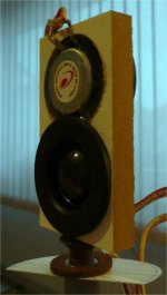
First, a graph and photo of the original On/Off axis FR and mounting method. Note there is 3dB/division vertically, and the graphs are 0, 30, 45, 60 and 90degs.
Now, look at the improvement with a more minimal mounting method (particularly at wide angles off axis):
Overall, the new TB driver (W4-1320sj) looks good. Pretty much comparable on and off axis behavior (with the more minimal mounting method), definitely lower distortion (measured, not necessarily audible), but still a little more expensive. I listened to a single driver in mono (with a healthy dose of EQ) for several hours last night - actually not bad! No buzzing, which is nice. My only concern is the drivers low sensitivity combined with its low power handling - I may burn it at some point. We'll see - if that happens, I go back to the Alpha6a, or with a 4-way...
Enjoy!
So, some measurements.
I EQ'd the raw driver response a bit, getting it approximately flat. I was a little surprised by the off axis measurements, not being better than the TB W4-656sc, so I dug a little deeper. What I found is inline with what StigErik has been getting into - that the mounting method matters (I haven't tried his suspended driver method yet, but I think the following supports his position).
First, a graph and photo of the original On/Off axis FR and mounting method. Note there is 3dB/division vertically, and the graphs are 0, 30, 45, 60 and 90degs.
An externally hosted image should be here but it was not working when we last tested it.
An externally hosted image should be here but it was not working when we last tested it.
Now, look at the improvement with a more minimal mounting method (particularly at wide angles off axis):
An externally hosted image should be here but it was not working when we last tested it.
An externally hosted image should be here but it was not working when we last tested it.
Overall, the new TB driver (W4-1320sj) looks good. Pretty much comparable on and off axis behavior (with the more minimal mounting method), definitely lower distortion (measured, not necessarily audible), but still a little more expensive. I listened to a single driver in mono (with a healthy dose of EQ) for several hours last night - actually not bad! No buzzing, which is nice. My only concern is the drivers low sensitivity combined with its low power handling - I may burn it at some point. We'll see - if that happens, I go back to the Alpha6a, or with a 4-way...
Enjoy!
At what side did you do the measurements with the initial mounting? On the left there is an extra wooden bar against which there might be a reflection. I'm am curious what exactly makes the difference here.
Hi Keyser,
I did the off axis measurements with the extra wooden piece turning away from the mic (if that makes sense). Either way, the less stuff behind the cone, the better.
I did the off axis measurements with the extra wooden piece turning away from the mic (if that makes sense). Either way, the less stuff behind the cone, the better.
SO! Here is what I've been trying to get at for some time.
This is the Neo3PDR tweeter and TB W4-1320sj, fully EQ'd. The lines represent 0, 30, 45 and 60deg off axis. I've set the listening axis at 30deg (the brown line), hence it is flattest. The XO is LR4 (acoustic) at 1700Hz. Ignore the regions below 250Hz and above 20k - they are invalid.
The goal of this thread has been to get the smoothest transition between mid and tweeter possible. I feel like I'm there.
Any comments?
PS - here is the individual drivers and then combined (at 30deg):
Soundeasy really makes it easy to achieve target functions...
An externally hosted image should be here but it was not working when we last tested it.
This is the Neo3PDR tweeter and TB W4-1320sj, fully EQ'd. The lines represent 0, 30, 45 and 60deg off axis. I've set the listening axis at 30deg (the brown line), hence it is flattest. The XO is LR4 (acoustic) at 1700Hz. Ignore the regions below 250Hz and above 20k - they are invalid.
The goal of this thread has been to get the smoothest transition between mid and tweeter possible. I feel like I'm there.
Any comments?
PS - here is the individual drivers and then combined (at 30deg):
An externally hosted image should be here but it was not working when we last tested it.
Soundeasy really makes it easy to achieve target functions...
Cuibono,
Thanks for sharing your TB investigation ! I happen to have a pair of 3" TB so your experience has given me something to do on the weekend !!
You seem to cross to Neo at about 1.6kHz. Is this not straining that tweeter?
Cheers.
Thanks for sharing your TB investigation ! I happen to have a pair of 3" TB so your experience has given me something to do on the weekend !!
You seem to cross to Neo at about 1.6kHz. Is this not straining that tweeter?
Cheers.
This looks near perfect! I think I'll reconsider the AL170. However, power handling probably is an issue with this TB. How are you planning to integrate it to a woofer?
Thanks everyone! I'm glad you enjoyed seeing it.
Gainphile - I've been using the Neo3 XO'd at 1700Hz since I've had them - I haven't noticed any strain yet. We'll see though (I'm more worried about the mid).
Keyser - Yes, there is a woofer involved. I XO between woofer and mid at 275Hz, LR4. The woofer is my own design, which there is a thread here somewhere ("another sensitive dipole woofer" or something like that)
Bruce - I can post them, but there is a bit of EQ involved. I use a computer and some studio software, but anyone else can do the same. I'll have to give a good write up on it, it took me a while to develop the software/hardware end of things. One thing though, is that even if someone replicates what I've done exactly, it is probably necessary to do final in-room measurements to get things really tight.
Beg your pardon, cuibono
but since everybody is showing his dipole tweeter measurements in your thread, I dare to throw in another one:

I placed two Dayton ND20FA-6 back to back on a small baffle (8 x 4.5 x 1.2 cm) and got this horizontal response (0, 15, 30, 45, 60, 75, 90 deg), measured at 45 cm distance (not calibrated):

There is no EQ involved apart from a 12 dB/oct HP at 2.5 kHz. For sure the vertical response is a mess and this botch will not find its way into 'production'. But it shows how mounting two very small tweeters very tight together can take you a loong way.
but since everybody is showing his dipole tweeter measurements in your thread, I dare to throw in another one:
I placed two Dayton ND20FA-6 back to back on a small baffle (8 x 4.5 x 1.2 cm) and got this horizontal response (0, 15, 30, 45, 60, 75, 90 deg), measured at 45 cm distance (not calibrated):
There is no EQ involved apart from a 12 dB/oct HP at 2.5 kHz. For sure the vertical response is a mess and this botch will not find its way into 'production'. But it shows how mounting two very small tweeters very tight together can take you a loong way.
Attachments
Thanks, those do look really good! I hadn't thought of mounting them that way, I guess because I think the figure of 8 pattern would be pointing at the floor somewhat. But tell us how it sounds, it looks really good so far!
I like your 'turntable' too.
I like your 'turntable' too.
What if you tilt the dual tweeter construction a little backward, so that the domes are in the same horizontal plane?
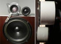
They should behave rather well between 15 deg up and down, but have severe notches from 10 kHz up at 60°. My 'real' attempt is with the same drivers mounted on axis back-to-back, as you can see in the picture - the smaller one to the right and bottom. Size is 4.5 cm dia and 3.3 cm depth.I hadn't thought of mounting them that way, I guess because I think the figure of 8 pattern would be pointing at the floor somewhat.
I've only listened to test noise yet and - as said - I did this configuration only for some impressive measurement curves. 😛But tell us how it sounds, it looks really good so far!
If the more serious second configuration lives up to expections I will do some real listening. Sadly I don't have any BG Neo3 to compare.
Yeah, probably the first lazy Susan for tweeters only ... 😀I like your 'turntable' too.
Good idea. I had not thought about it yet. The voice coils should be within millimeters already. I am not sure if the acoustic centre is supposed to be much in front of the VC.What if you tilt the dual tweeter construction a little backward, so that the domes are in the same horizontal plane?
Attachments
Hi Rudolf,
Looks cool - please post the polars sometime for your little back to back tweeter, if you can. I'm interested in seeing them, as I was surprised how poorly my back to back tweeters did, in terms of off axis regularity.
Looks cool - please post the polars sometime for your little back to back tweeter, if you can. I'm interested in seeing them, as I was surprised how poorly my back to back tweeters did, in terms of off axis regularity.
- please post the polars sometime for your little back to back tweeter ...
What a dissapointment!
I measured the back-to-back tweeter and just afterwards the tweeters in that small baffle again. I must have changed something with the EQ, because the treble falls of earlier than in my first measurements. But both last measurements are 100% comparable.
I measured the length from the rear dome center to the front plane of the front tweeter. This should be indicative of the dipole length. I got 5.6 cm for the back-to-back and 3.8 cm for the offset drivers. This corresponds to full wavelength of 6125 Hz and 9026 Hz. Quite near where the diagrams have their on-axis dents, because the backwave is 360deg out of phase with the front wave.
You will not be surprised that I will dig deeper into that flat baffle thing again ...
Attachments
Hmmm, too bad. The back-to-back response looks like mine. Basically unusable. I'm surprised what a difference there is between the b2b tweeters and the Neo3. I wonder what makes the difference?
The b2b tweeters are almost ideal dipoles - circular point sources - and hence show the strong dipole peak/nulls. The Neo3 is a square diaphragm, and the frame shape and grill may have something to do with it. Recently, I added a rectangular frame between b2b tweeters, but it didn't help. I just hope BG doesn't go under anytime soon!
The b2b tweeters are almost ideal dipoles - circular point sources - and hence show the strong dipole peak/nulls. The Neo3 is a square diaphragm, and the frame shape and grill may have something to do with it. Recently, I added a rectangular frame between b2b tweeters, but it didn't help. I just hope BG doesn't go under anytime soon!
It is the dipole length, like the red lines in the picture. It is 5.6 cm for my b2b, 4.1 cm for the Neo3 and 3.8 cm for the offset baffle. That's why that little baffle looks a bit better (on paper) than the Neo3, and the b2bs look a lot worse. A variation of the dipole length around the perimeter may be helpful too IMHO. It is provided by rectangular configurations, but not by the b2b tweeter.I'm surprised what a difference there is between the b2b tweeters and the Neo3. I wonder what makes the difference?
Attachments

The thing I am surprised with is more the regularity (or irregularity) of the off axis response - Why would the Neo3 be so regular, while the b2b tweeter not? It isn't the shape of the frame....
Hi to all,
Great investigation job 😉
Just my 2 cents and some idea, the tweeter should be better flush mount ?
Back to back tweeter in a tube flush mount like this ?
In the treble shapes must be very smooth
Have fun 🙂
Great investigation job 😉
Just my 2 cents and some idea, the tweeter should be better flush mount ?
Back to back tweeter in a tube flush mount like this ?
An externally hosted image should be here but it was not working when we last tested it.
In the treble shapes must be very smooth
Have fun 🙂
Sure. This is just a test bed for first investigations ... the final thing should be more sophisticated.the tweeter should be better flush mount?
Look at the picture in post #52. Those are b2b tweeters in a tube.Back to back tweeter in a tube flush mount like this?
Smoother than shown, yes. But I would not add any mm to the sides to round them off. This would be detrimental to the dipole length.In the treble shapes must be very smooth
Rudolf
Thanks Rudolf for the response, I did not understand the picture post #52. The result is not very good. I wonder why this is so bad. Perhaps the solution to improve the waveform, by improving the shape ?
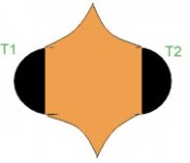
I think about an inverse horn ? The path of the dipole length is higher but the dispersion could be better. A shape like this : (T1 and T2 are the tweeter.)
I think about an inverse horn ? The path of the dipole length is higher but the dispersion could be better. A shape like this : (T1 and T2 are the tweeter.)
Attachments
- Status
- Not open for further replies.
- Home
- Loudspeakers
- Multi-Way
- 'Very' OB Midrange Baffle Width Study