Well given that I had to borrow the rectifier tube from another unit, seems I need another one anyway, so I will get a new one and report back.
Are these Copper Cap rectifiers
http://www.webervst.com/ccap.html
a worthwhile substitute?
thanks
Kirk
Are these Copper Cap rectifiers
http://www.webervst.com/ccap.html
a worthwhile substitute?
thanks
Kirk
I've often heard it reported that modern made rectifier tubes aren't as good as the old ones. Considering the 6CA4 was running right at the limit in this circuit, I'm not sure how well a new construction tube is going to fare. Of course, old stock tubes are stupid expensive.
I've heard favorable reports from Weber Copper Cap users. If you don't mind the $22 price, I think it would be an excellent option for your amp. It's plug and play easy, and should outlive the rest of the amp. If the price tag is more than you want to spend for this old amp, then just build your own solid state rectifier out of a pair of UF4007, a CL-90, and a suitably sized cemented power resistor.
I've heard favorable reports from Weber Copper Cap users. If you don't mind the $22 price, I think it would be an excellent option for your amp. It's plug and play easy, and should outlive the rest of the amp. If the price tag is more than you want to spend for this old amp, then just build your own solid state rectifier out of a pair of UF4007, a CL-90, and a suitably sized cemented power resistor.
kirk57 said:voltage coming off the secondary is 544v
Off the first filter cap it's 305
off the second filter cap 303v
The reading you took off the power transformer secondary - I'm assuming that is with your meter set to AC, taken between pins 7 and 1 on the rectifier tube?
Ty_Bower said:
The reading you took off the power transformer secondary - I'm assuming that is with your meter set to AC, taken between pins 7 and 1 on the rectifier tube?
yep, just checked it again, 555 volts ac between pins 1 and 7 of the rectifier tube.
I'm gonna get the copper cap. I'll let you know what the result is.
Kirk
kirk57 said:the first filter cap...
...the others rated to 350v.
kirk57 said:yep, just checked it again, 555 volts ac between pins 1 and 7 of the rectifier tube.
OK. Forget what I said about your power supply being the same as the PSU in the KN728. Clearly, the KN728 runs the finals at a higher voltage. It has a 640 volt secondary winding on the PT (320-0-320), and yours has a ~550 volt winding (275-0-275).
...not to mention that I had forgotten the KN928 power supply is identical to the KN724, as you and Carsten had already discovered back in post #26.
If you want to substitute the EZ81 with your own work...and don´t want to spent mega-bucks: 130mA, ~24V rectifier drop...so, you need a 220R@>=11W Wirewound ceramic coffin (or 4-5x 1K-2W MOX) as R64 in the Knight 728b-schematic if you chosse to substitute EZ81 with 2xUF400x (or even better BYV96e).
Carsten
Carsten
OK I got the copper cap to replace the 6CA4, plugged it in, and the result is the same as before ..very low volume.
I'm more than happy to replace parts, but not sure which parts to replace!
I'm more than happy to replace parts, but not sure which parts to replace!
I'm still puzzling over this one. I guess we can rule out a weak rectifier tube. From one of your previous posts, you said the voltage swing at the speaker side of the output transformer was roughly the same as the voltage swing at the input (grid) of the 6BQ5 tubes. This can't be right. The last stage needs to have some gain if you're going to get 10~12 watts out of this thing.
You could try taking a closer look at the bypass capacitor across the output tubes' cathode resistor. I think you said it was a 10uF part on your amp. If you are looking at the KN728B schematic, it is the cap labeled C1. I'm pretty sure that if this cap dries up and goes completely open, you'll lose a lot of gain on this stage. You can get a cap that's "close enough" from the local Radio Shack. Maybe something like this 47uF, 35V cap or maybe this 100uF, 50V cap would work. The stock 10 uF part seems a little small to me - probably a cost savings measure. But, I wouldn't get crazy with the capacitance on this part, probably no more than 100 uF is fine. Keep the voltage rating at least 35V or more. If you can find something close to the original 50V rating all the better. Think about whether you want it axial lead or radial lead for easy mounting. You'll need to strap it in parallel across the existing cap and cathode resistor.
I'm also puzzled why you said the amp first went weak in one channel, and then the other. This cap is common to both channels, so if it were bad then both channels should have gone out at the same time. Are you confident the output tubes themselves are strong? Have you swapped in any other 6BQ5 tubes?
edit... oh, and one more thing. If you do decide to try to solder in another bypass cap in parallel across the 100 ohm cathode resistor, be sure to remember that electrolytic capacitors are polarized! It is critical you get the plus and minus ends of the cap soldered in the right places.
Kirk,
I know that troubleshooting can be very frustrating...but sometimes the problem, after all this time, can be very obvious! I've read this thread a couple of times, and there are a couple of things that have been missed (unless I'm not reading it correctly).
First of all, I would check and reheat all of the soldering joints...pull on the wires of every one of them to make sure they're all secure and connected properly.
Second....For about $50 you can buy all new tubes for it. Some tubes (especially old ones), can work well in one circuit and not in another. This way, you can completely rule out any weak tubes.
Good luck!
John.
Ty-
I unsoldered the connections to the 10uF 50v cap and measured
it's resistance...it's on the order of 8M, so I assume it's not shorted. Should I still replace it? I do have some 47uF 50v caps.
John-
I checked for cold solder joints and don't see any.
I'm going to try completely retubing this and see if
that helps, but I've tried these tubes in my Peavey Classic
20 and they work there. Of course distortion is desirable in that amp, so maybe that's not a good test....
Kirk
Since you've got the part, give it a try. Just make sure the minus end of your cap is the side that gets soldered to ground.
There must be something wrong with the output stage of the amp. You need to be able to get at least a 25 volt swing off the speaker side of the output transformers if the amp is going to make full power. You shouldn't be seeing a two volt swing for a two volt input - there's no gain there.
It might be worthwhile to use your ohmmeter and verify the resistors around the output stage are still close (+/- 20%) of their rated values.
Here's an update:
I did not replace the capacitor as
recommended, trying for the easy fix (of course that did not work)
I got all new tubes and plugged them in. Unit now had very pronounced hum, and two of the el84 got very hot very quickly,
and something smelled bad...so after about 30 seconds I unplugged it. So the result *is* different, but not better, and I also noticed that the top of the (old) tubes in those 2 el84 is black instead of silver which I understand may indicate a problem.
I've ordered all new filter caps for this, and checked the resistor
values, none are more than 20% high, but as long as I had one
side unsoldered I replaced any that were more than 10% out.
When I get the caps installed I'll report back.
Are you sure your still getting around a 10V reading at the cathodes of the 6BQ5's? That's a very good indication that C1, the 50 uF section used as the cathode bypass capacitor across the 100 Ω resistor, has shorted. The outputs are running very hot....you've got a bias problem somewhere. This in turn is overloading the PT, which is probably why you're getting hum and a funny smell. Don't put in those new tubes until you find out exactly what's wrong....or the new ones will be toast as well!
The Sam's Photofact website has the KN734 schematic download for $22. You will have the values and voltages for that EXACT amp.
The Sam's Photofact website has the KN734 schematic download for $22. You will have the values and voltages for that EXACT amp.
TubeHead's advice is sound. Make sure your bias is good, and the new tubes are running away (over conducting). Cherry red plates are bad.
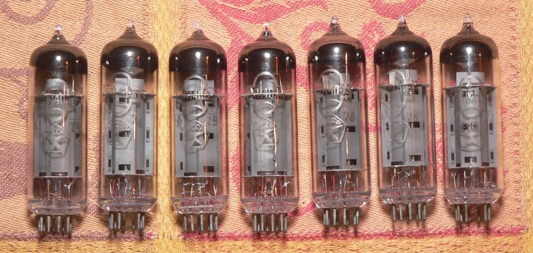
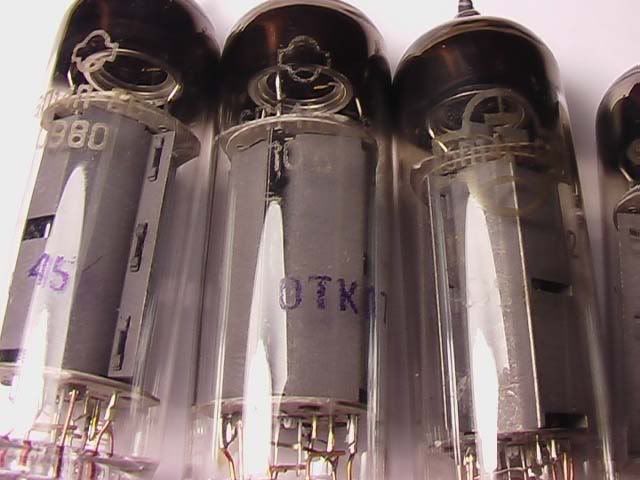
I've got a bunch of EL84 tubes with black getter flashing (instead of silver). They seem to work fine for me. I think powdery white getter flash is bad (air in the tube), but silver or black is OK. Some getter flash is brown, and that's OK too.
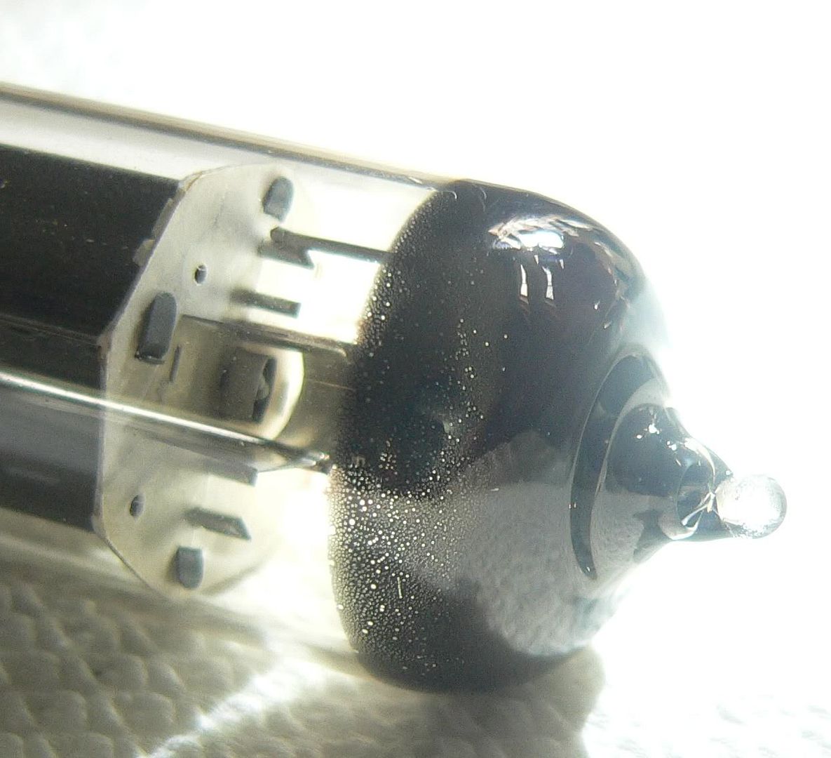
Here's an odd 6p14p (EL84 equivalent) with what appears to be tiny pinholes in the getter flash. It also appears to be black. This tube works perfectly well, although I don't know what caused the pinholes. Perhaps it was that way since new, and I never noticed before.

I've got a bunch of EL84 tubes with black getter flashing (instead of silver). They seem to work fine for me. I think powdery white getter flash is bad (air in the tube), but silver or black is OK. Some getter flash is brown, and that's OK too.
Here's an odd 6p14p (EL84 equivalent) with what appears to be tiny pinholes in the getter flash. It also appears to be black. This tube works perfectly well, although I don't know what caused the pinholes. Perhaps it was that way since new, and I never noticed before.
The Good:
I got the new filter caps installed, and now I am getting pretty good volume, still needs to be halfway up or so to get going but that's OK. Now using ADS L400s that somebody threw away over the weekend; maybe not the most effiecient speaker out there.
The Bad:
There is a persistent buzz (NOT 60Hz hum) that can be largely eliminated by me touching the chassis ...assume this is a ground problem. I checked voltage between the ground connection of the outlet and the chassis of the amp, and it's ~ 6 volts plugged in one way, and ~65 v the other way! Would it be a good idea to put a grounded plug on this, and if so, does the green connection get screwed the chassis? I assume I would want to orient the plug for the lower of the 2 chassis-to-ground readings.
The Weird:
As mentioned, I bought all new tubes, the EL84s are JJs, the tubes that were originally in there are Raytheon 6BQ5s. With 6BQ5s everything is OK, but when I use the EL84 in the socket for what I've been calling tube 1, it the plate gets cherry red and distorts, smells bad, etc. I tried it with several different EL-84s and the result is the same, but it does *not* happen with the 6BQ5. Why would this be? I can use the EL84 in all the other positions and they are fine (though I think the Raytheons may sound a bit better...)
kirk57 said:The Good:
I got the new filter caps installed, and now I am getting pretty good volume, still needs to be halfway up or so to get going but that's OK. Now using ADS L400s that somebody threw away over the weekend; maybe not the most effiecient speaker out there.
The Bad:
There is a persistent buzz (NOT 60Hz hum) that can be largely eliminated by me touching the chassis ...assume this is a ground problem. I checked voltage between the ground connection of the outlet and the chassis of the amp, and it's ~ 6 volts plugged in one way, and ~65 v the other way! Would it be a good idea to put a grounded plug on this, and if so, does the green connection get screwed the chassis? I assume I would want to orient the plug for the lower of the 2 chassis-to-ground readings.
The Weird:
As mentioned, I bought all new tubes, the EL84s are JJs, the tubes that were originally in there are Raytheon 6BQ5s. With 6BQ5s everything is OK, but when I use the EL84 in the socket for what I've been calling tube 1, it the plate gets cherry red and distorts, smells bad, etc. I tried it with several different EL-84s and the result is the same, but it does *not* happen with the 6BQ5. Why would this be? I can use the EL84 in all the other positions and they are fine (though I think the Raytheons may sound a bit better...)
 Yes, orient for lowest measured voltage to ground. Look for a cap or resistor (or both) from ac line to chassis and immediately remove it!
A 3 wire grounded cord is a good long term investment in your health.. Ground conductor should go directly to the chassis via a lug,
in the event of a ground loop you will need to figure out a solution that provides the required safety ground and breaks the ground loop. (I decided to remove specific instructions on how to do this, as there may be a hazard in the event of simultaneous failures of a component connected to the ac line, and one of the components in the protective network.)
Old 6BQ5 often seem far more rugged than the current production JJ and others which meet the spec with no margin to spare. I use Russian made 6P14P-EV which are more similar to the old 7189 and can take considerably more abuse. Most vintage amplifiers running these tubes run the tubes well beyond the recommended ratings in order to squeeze the most power out of them possible, and when you factor in the generally higher line voltages present today you can see plate voltages and currents that can be substantially beyond maximum design values simultaneously.
The cathodes of all four output tubes are tied together through a single, shared ~100 ohm 7 watt resistor leading to ground. If one tube "decides" to pull more current, then the other three will end up getting less. You need to have relatively well matched output tubes for it to work well. Going off the KN728B schematic, 12 volts across 100 ohms is 120 mA shared between four tubes. Assume perfect matching, and each one is dissipating (370 volts - 12 volts) * 30 mA, which is 10.75 watts. In reality, they're probably not going to all pull the same current. I have an amp where one tube will get 20 mA while the other gets 40 mA. Maybe there's a little bit of corrosion on pin 3 of some of the sockets, so their resistance is a little higher. Then the socket with the cleanest cathode pin is going to get more than its fair share of current. Try shooting some DeOxit D100 in the tube sockets, if you have any.
I'd recommend taking out the 100 ohm resistor, and replacing it with four individual 400 ohm resistors. Better yet, make them 470 ohm and let your tubes run a little easier. The resistors should probably be rated for 2 watts (each). You need to bypass each of those 470 ohm resistors with a capacitor rated for 25 volts or greater. 20uF to 50uF would be about right. The tricky thing will be finding enough room under the chassis for all the new parts.
I'll agree with Kevin on the old 80's vintage Russian 6p14p tubes. I like the military rated -EV version, and even the "standard grade" is a fine tube. I'm running 390 volts across them (cathode to anode) with 32 mA current (plate + screen) and they're holding up fine. I've got no experience with the new production EL84 tubes.

Kevin-
I'll install the 3-prong plug; as long as I'm there would it be wise to add an in-line fuse? (there is none as it is) If so, which side to fuse, and I think I've read 3 amp is a good value; does that sound right?
Ty-
Does it matter if the new caps are electrolytics or something a bit better, or is that only an issue for cases where the signal passes through the cap?
The JJ tubes are matched (at least they all had 21/5.4 written on the box) I don't have any DeOxit, would regular Radio Shack contact cleaner work? How about using pipe cleaners to clean the sockets (after discharging the filter caps)
Kirk
kirk57 said:Kevin-
I'll install the 3-prong plug; as long as I'm there would it be wise to add an in-line fuse? (there is none as it is) If so, which side to fuse, and I think I've read 3 amp is a good value; does that sound right?
Ty-
Does it matter if the new caps are electrolytics or something a bit better, or is that only an issue for cases where the signal passes through the cap?
The JJ tubes are matched (at least they all had 21/5.4 written on the box) I don't have any DeOxit, would regular Radio Shack contact cleaner work? How about using pipe cleaners to clean the sockets (after discharging the filter caps)
Kirk
Hi Kirk,
Yes definitely add a fuse and this should be on the hot side of the line - usually the black wire in a US spec 3 wire cordset.. White is neutral, green is safety ground. The hot should first see the fuse, then the switch and finally the primary of the power transformer. The white goes to the low end of the transformer. (Identify the orientation that gives the lowest leakage with the old 2 wire cord and any death cap and resistors removed - trace the neutral back to the transformer - this should be the low side of the primary.)
Use electrolytics for the cathode bypasses and I would probably do what Ty suggests or at least make the cathode bias per stereo channel. (200 ohm 5W resistor) Increasing the resistance slightly to reduce idle current probably would not hurt. I'd use 220 - 240 ohms per stereo channel or 470 ohms for individual tubes per Ty's suggestion. I would probably use 100uF/35V caps (stereo pairs) or 47uF/35V (singles) to provide some voltage rating margin in the event of a bad tube induced fault.
Signal caps should be good quality films with voltage ratings higher than or equal to the originals, and the same value unless you understand how changing the coupling cap values might or might not affect the LF loop stability. Matching pairs of coupling caps may help reduce LF distortion by improving balance in the output stage, but aren't necessary.
- Status
- Not open for further replies.
- Home
- Amplifiers
- Tubes / Valves
- Very low output from Knight KN928 amp