> OK I've uploaded the pics to Photobucket:
Very useful photos.
> A couple of things: I was right the first time, the bypass cap is
>10uf 50v, not 50uf.
This KN928 seems like a lower performance version of the KN734. Nothing wrong with that, but they probably saved a few nickels going with a smaller cap. I wouldn't worry about it for now. Maybe after it's working again, some of these items can get revisited.
>If I replace the 47k resistor, what power rating should I get?
>Is quality an issue here? (i.e. metal film vs carbon vs unobtainium
>$50 resistors from the back of the Absolute Sound?)
Assuming we're talking about R55, you'd be fine with a 1/2 watt. There's no real power moving through there. Even a 1/4 watt might do. In what way did the old one fail?
>Looking at the KN-734, I see what looks like 2 12ax7s, but that's
>actually one isn't it? The diagram shows each one as a triode,
>but this tube is a dual triode as I understand. Am I reading this
>right?
Yup. Two triodes inside one bottle. The schematics routinely show only half the tube if that is all that is being used for that piece of the circuit.
>I'm gonna owe you a case of beer (assuming you like beer that is)
Love the stuff.
I'm still trying to figure out where the problem lies. The only voltage that looks odd to me is the ~20 volt reading you see on the grid (pin 2) of 12AX7 #1 and #2. Can you recheck these? Measure the voltage with respect to the cathode (pin 3), not ground. The grid should be sitting about one half to one volt lower than the cathode. Make sure the amp's inputs are shorted, or the volume knob is turned all the way to the minimum setting while you're checking this. You don't want a signal running through the tube while you're trying to check idle voltages.
Check this and see if it is close.

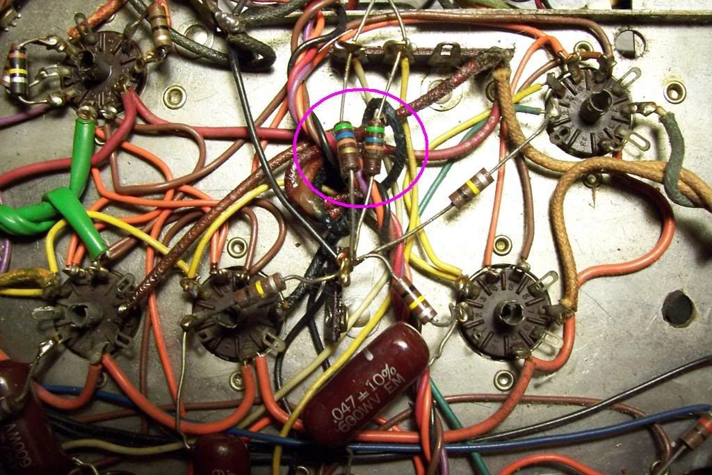
I can't see R48 in your photos, but it shouldn't be hard for you to find. C26 is the light brown ceramic disc cap sticking straight up in your photo. I'm assuming it's a .047 since I can't read its numbers.
I've been deliberately ignoring the two 12AX7 tubes in the far corner (#3 and #4, as you call them). One half of them is almost certainly used for the phono preamp. The other half is probably used to make up for losses in the bass and treble controls. If the stage that provides the gain for the tone controls is whacked, that might be responsible for your low volume. But first, I'm still curious as to why you see 20 volts where is should be closer to 60 (on the PI).
R48 is most likely a 47k part, same as R49?
Try to figure out what voltage is on either side of R49. You already know the voltage on one side is 240V (at pin 1 of 'X7 #1/#2). I'd like to know how many volts are on the other side, or how many volts are dropped across it. Max plate current for the 'X7 is 1.2mA. There could be as much as 55 volts dropped across R49, but something tells me that tube isn't conducting as much as it should be.
Try to figure out what voltage is on either side of R49. You already know the voltage on one side is 240V (at pin 1 of 'X7 #1/#2). I'd like to know how many volts are on the other side, or how many volts are dropped across it. Max plate current for the 'X7 is 1.2mA. There could be as much as 55 volts dropped across R49, but something tells me that tube isn't conducting as much as it should be.
OK I replaced R55 with a 1/4 watt resistor for now (I'll put a 1/2 watt in there when I get one). The old one was physically broken, the lead had come off the body. No apparent change in volume
with this change.
I measured the voltages on 12ax7-1, this time wrt pin 3
(previously I had done this wrt ground)
I think these are the readings you'd expect?
pin1 177v
pin2 -1.15
12ax7-2
pin1 182
pin2 -1.12
As far as C26...the ceramic disk cap between pin 2 and 6 has these markings:
RMC - This is the manufacturer I think?
.01 .01uf
Z5U is this tolerance?
57 volts are dropped across R49
I am not seeing R48..is it possible it's not there?
I tried using headphones to listen instead of these tiny monitors,
I can defininitely hum 60 hz hum through the phones (I don't think the speakers go that low!)
This means I need to replace the filter caps?
Here is another Knight 724 circuit:
http://wb9k.tripod.com/
Sorry for hijacking your thread, but please can you give me the correct values for the RC-circuits behind 6c4/EZ81?
I have a Knight 735 on my workbench...somebody has make the attempt to better the original circuit with much higher C´s....but as far as I can see without knowledge....and maybee some false connections.
So...for you, it could be a great learning excercise to take a look at the original circuit and post the original values...this will help others.
Regards, Carsten
PS: the 47k from the opt is located in a feedbackloop (for better performance)...1/2W is enough.
Carsten-
I checked and the RC values on my KN928 are exactly the same
as those shown on the stock power supply on the 724 page you provided a link to.
At this point I'm confused. It seems like the voltages and DC resistance of the filter caps are OK, but I'm hearing hum through
my headphones that might indicate the filter caps are bad.
Should I replace both cans? Looks like close to $70 in parts
from Antique Electronic supply (www.tubesandmore.com)
to do both.
Kirk
Kirk57, of all the things you tried, i would most definitly replace the filter capacitor, but also check that 6CA4 tube. When you tried it on that Knight 680 tuner, that tuner does not draw the current that a power amplifier draws, so if you can, get another 6CA4 tube.
Replacing the filter cap probably isn't a bad idea, simply due to its age. But, seeing reasonable looking voltages in the power supply, output stage, phase inverter, and AF amp suggest to me there is still a problem somewhere else.
Swapping the 6CA4 again surely can't hurt anything. I certainly agree that a tuner probably doesn't put the same kind of load on the rectifier as a quad of hungry EL84. But again, the voltages seem to check out. If the 6CA4 were dying, wouldn't we see a lot of voltage drop? 320 volts on the plate sure seems right to me.
Kirk mentioned he has an old single channel oscilloscope. I'm wondering if it would be worthwhile to try using it to diagnose where the problem lies. I'm thinking the signal path through this amp goes something like this:
line in > select switch > 1/2 'X7 > tone > volume > AF > PI > EL84
The line in from a CD player, etc. goes through an input selector switch. Then it passes through a first stage audio frequency amplifier (gain stage) which is built out of half a 12AX7. Then it goes through the tone controls (bass & treble), then through the volume control. After that it goes into the next AF amp, the phase inverter, and finally the EL84 outputs.
We've already looked at the AF/PI/output stages and I didn't notice anything glaring. If you feed a signal into the input, then carefully choose places to stick your 'scope probe, you should be able to see the signal as it goes through the amp. It might be smart to check the point you intend to probe to see if there is any significant DC offset, or large AC swings before you stick your 'scope probe on it. No sense frying the scope, or yourself.
The input should be easy enough to scope out. I figure you'll have a waveform somewhere on the order of +/- a several tenths of a volt, depending on your input source. I'd think you'd have the same signal immediately after the input selector switch.
Finding the first gain stage (immediately before the tone controls) might be a little tricky. We haven't really looked for it yet - there might not be one there. Looking at the photo of the 'X7s in the corner (#3 and #4) it seems like one half of each triode is cap coupled straight into the other half. This suggests to me that the whole tube is used up for the phono pre-amp, and there are no triodes left over for a pre-tone control gain stage.
If there is one, then it will probably have a ceramic disc cap coming off either pin 1 or 6, which will then lead into the tone control circuitry. You don't really want to stick the scope probe directly on pin 1 or 6, as there is probably 120 volts DC there. On the other side of that cap it should be nearly 0 volts DC, but with an AC signal on it. That's where you want to put the scope. This signal should be greater in amplitude than the original input signal.
After the tone controls, the signal should be smaller in magnitude than it was going in. After the volume control, the signal might be anywhere from equal (at maximum clockwise rotation of the volume knob) to nearly zero (at minimum clockwise rotation).
You should be able to safely probe at pin 7 of 12AX7 #1 and #2. This signal is the input to this tube, and should be +/- 1.0 volt. In fact, this is probably the first place you should starting probing. If you can't get a signal approaching +/- at least a tenth of a volt or so, I'm going to wonder why. You can also check the signal at pin 2 (or pin 1 on the oddball) of the EL84 tubes. This signal is going to be several times greater than it was going into the AF/PI stage.
Be careful probing. I'm going to stare at the photo of #3 and #4 tubes and see if I can figure out how they are connected. I've updated my drawing of the AF/PI stage slightly - can you spot any mistakes? It's hard for me to see where all the pieces go, since some parts go underneath others.

Ty-
OK I'll get the scope out.
I hope this doesn't lead to a "need help to repair vintage B&K scope" thread....
Kirk
OK I'll get the scope out.
I hope this doesn't lead to a "need help to repair vintage B&K scope" thread....
Kirk
Ty-
Regarding your updated drawing of the AF/PI stage:
- I don't think R45 exists?
- The disk cap bypassng R44 is labeled 68NF750 10%
which I assume is 68 nanofarad , 10% tolerance. Don't know
what the 750 means...
Kirk
Regarding your updated drawing of the AF/PI stage:
- I don't think R45 exists?
- The disk cap bypassng R44 is labeled 68NF750 10%
which I assume is 68 nanofarad , 10% tolerance. Don't know
what the 750 means...
Kirk
kirk57 said:I checked and the RC values on my KN928 are exactly the same
as those shown on the stock power supply on the 724 page you provided a link to.
....
Should I replace both cans? Looks like close to $70 in parts
from Antique Electronic supply (www.tubesandmore.com)
to do both.
Thanks!
If you replace the caps: check the dimensions...most of the time they didn´t match your specific gear.
A cheap solution is to throw away the inside of the caps and refill them with 10/20/47µF axial caps for 10-15,-$.
6ca4/EZ81 isn´t cheap as a NOS valve...but JJ is producing them now for ~10,-$.
Carsten
Ty-
OK I traced the wire from pin 8 to R45 (56K) so yes it's there.
The 'scope is working. I measured the input (using an iPod)
at 0.2 v p-p. But I am not seeing anything on pin 7 on either
1st or second 12ax7.
Pin 2 of the EL84s I do see signal, varies with the volume control.
With the speaker selector turned off, and cranked wide open
I'm seeing 2v p-p at pin 2
I must be taking the reading off the preamp tubes wrong.
I'm clipping the negative lead the the chassis and probing the pin with the positive lead. Is that the right way to do it?
Kirk
Your measurement technique sounds correct. The output of your iPod seems low to me. I thought most line level signals were ~ 1 volt. I might have to go check my CD player or something.
I'd think that a 2 volt input signal to the finals should give at least some kind of usable output. Let me see if I can figure out the math and calculate the (expected) gain of that stage. With your 2 volt input signal at the grids of the EL84, what kind of AC voltage do you see between the ground a 8 ohm speaker connections?
On a side note, tubes don't like to run with no load connected to the outputs. I'm surprised the speaker selector switch would allow you to switch off all the speakers. You should always keep a set of speakers connected, or use a "dummy" load - a 20 watt, 8 ohm, non-inductive, wirewound cemented resistor.
I've used the iPod to drive basic amps in lieu of a proper preamp and it works fine, so I think that part is OK.
I measured the AC voltage at the 8 ohm taps with the volume control wide open and believe it or not it's not that different than what I'm seeing at pin 2 of the output tubes, maybe even a little less! How can this be??
I've triple-checked....
BTW, I do have speakers connected to the amp when doing all these tests, but there is a speaker on/off switch on the front which I had turned off....doesn't seem to have done any harm as it's behaving the same now as before.
Yup, that's not gonna work. A two volt swing (peak to peak) across an 8 ohm load is not even a tenth of a watt.
Assuming a sine wave, take your peak voltage (one half of peak-to-peak) and divide it by the square root of two to get volts RMS. Power is given by (volts RMS)^2 / load impedance. 24 volts peak to peak is 12 volts peak, or ~ 8.5 volts RMS. 8.5 volts RMS into an 8 ohms load is 9 watts.
It seems like there is no gain on the finals. A two volt swing on the grid doesn't sound completely unreasonable, although I'd expect it could be a little greater than that.
Was gonna mention that it looks more like ~4v p-p on the grid, maybe that's more in line with what you'd expect.
Was gonna mention that it looks more like ~4v p-p on the grid, maybe that's more in line with what you'd expect.
korey said:I have an amp where the 6CA4 tube went bad (not shorted) and volume diminished drastically. Replacing it brought it back to full power.
korey said:...also check that 6CA4 tube. When you tried it on that Knight 680 tuner, that tuner does not draw the current that a power amplifier draws...
You ought to take another look at Korey's suggestion. He's right - a tuner isn't going to put the same kind of demand on the rectifier as a power hungry quad of 6BQ5 output tubes. The 6CA4 rectifier is really undersized for the needs of four 6BQ5 anyway. It's good for a single ended stereo 6BQ5 amp (two output tubes), but struggling for a push/pull design like yours. Typically, I'd rather see two 6CA4 rectifiers or better yet a single 5AR4 (GZ34), 5U4, or 5AS4. Of course, Knight opted not to use the stronger rectifiers because that would have required an additional 5 volt winding on the power transformer. The design they used is a compromise that probably saved them a nickel.
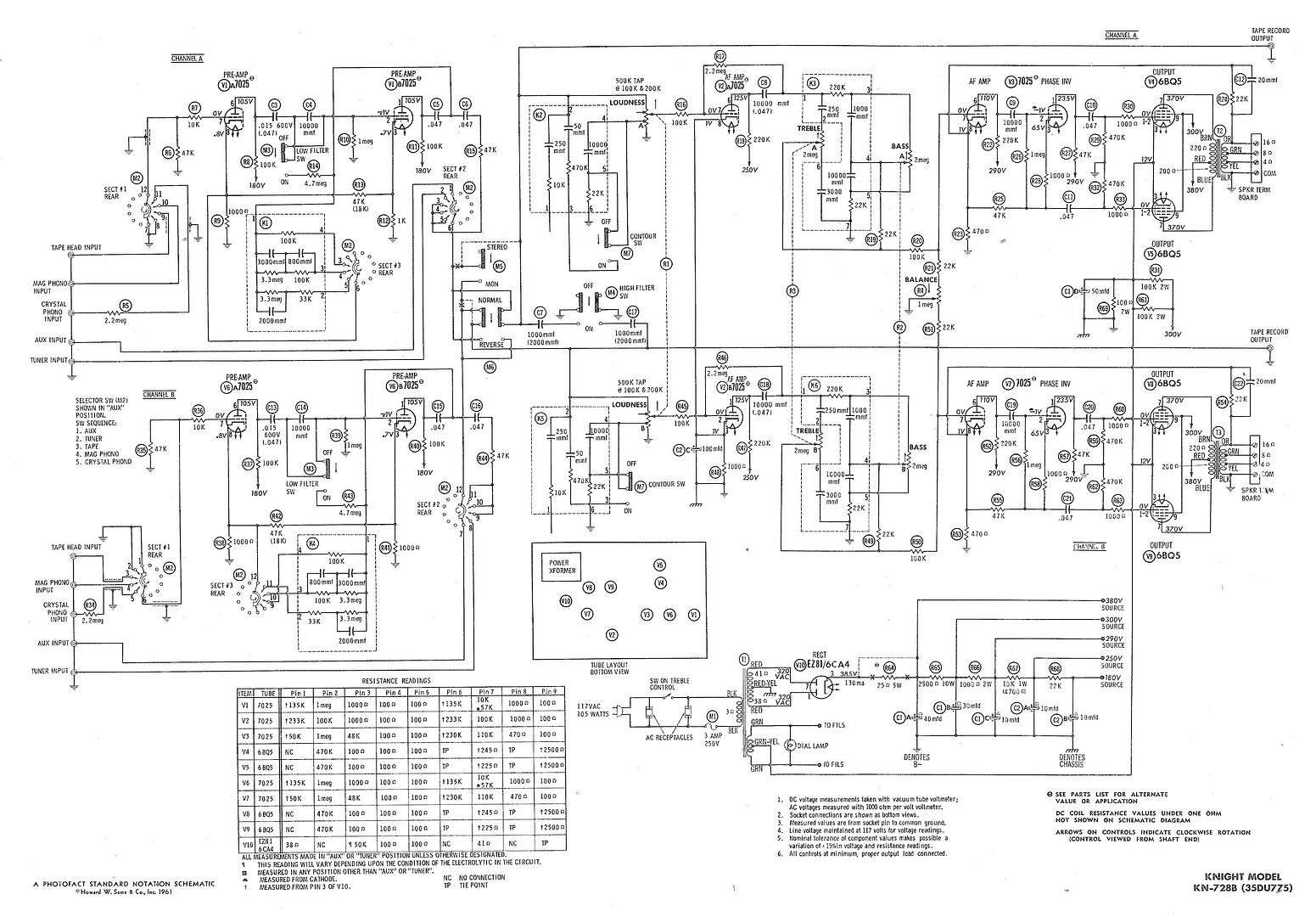
I have a friend who found the schematic for a Knight KN-728B. It still isn't exactly the same as your 928, but I think it's as close as we are ever gonna get. The output tubes are arranged the same, with the addition of a 1000 ohm grid stopper resistor (which I couldn't spot in the photos of yours). The rectifier uses the same 6CA4 tube, so I'd expect the rest of the power supply circuit is identical. The AF/PI stage looks awfully close to what I sketched up, except they show a 470 ohm resistor where I thought I saw a 5600 ohm part. I thought it was a green/blue/red. Maybe it's really a green/blue/brown, which is a 560 ohm. The 728 also uses an extra triode (half a 12AX7) immediately after the volume control, but before the bass & treble controls. I'm expecting your amplifier does not have this additional gain stage, so just ignore it on the schematic.
After seeing the KN728 schematic and noting the 370 volt specification on the output tube plates, it really makes me think maybe you do have a weak rectifier. You mentioned you have a variac. Do you happen to have any 1N4007 or UF4007 solid state diodes around? You might be able to get a couple at the Radio Shack. You can rig up a couple of these guys in place of the 6CA4 tube. One gets connected between pin 7 and 3, and the other diode goes between pin 1 and 3. Be very careful that the banded (striped) end of the diodes go together on pin 3. Mechanically, you'll have to be creative. You don't want the 6CA4 tube in the socket at the same time as the diodes. You can try stuffing the leads of the diodes into the tube socket holes, but be careful not to stress the fingers in the socket holes. You can also tack solder the diodes to the underside of the socket.
With the diodes in place and the 6CA4 out, bring up the amp very slowly on the variac. The solid state diodes will not have the same voltage drop as the vacuum tube rectifier, so watch the voltages on the power supply. You don't want to end up with more than 370 volts DC on the plates of the 6BQ5, as shown on the KN728 schematic. You also shouldn't need to use more than 117 VAC out of the variac.
- Status
- Not open for further replies.
- Home
- Amplifiers
- Tubes / Valves
- Very low output from Knight KN928 amp