Hi everyone,
I'm having a problem with an amplifier, because I'm having a simulated maximum THD1 of 0.04% at 4 ohm (~ 1W to 100W), and a maximum THD20 of almost 0.5% (typical levels 0.2-0.3%) which is terribly high, I don't know what it's causing this, but I suspect that the problem is the Cmiller capacitor that is too high, and is decreasing the slew rate, but I can't lower it and keeping the phase margin.
Can someone help me here?
Thank you very much for your concern,
Best regards,
Daniel Almeida
Attachments
what are the outputs biased at - should be >100 mA per Q for half decent crossover response
gate stoppers look 10x too big, driver Q underbiased too
other than that - you could try splitting the Ccomp for 2-pole
gate stoppers look 10x too big, driver Q underbiased too
other than that - you could try splitting the Ccomp for 2-pole
Thank you very much for your help,
outputs are biased at 150 mA per Mosfet, I used that value of Rgate because that's the value used in the Bob Cordell's design in which this amplifier is based. Driver bias current is 24 mA. I don't understand two pole splitting, there is any formula, pole splitting isn't more unstable?
Best regards,
Daniel Almeida
Maybe try halving the input ltp source degen resistors R17 n its partner and then sim what happens ?
Thank you for your advice,
I've tried to do that and increases the open loop gain, ruining phase margin, and does the oposite, increases THD.
🙁
Best regards,
Daniel Almeida
I've tried to do that and increases the open loop gain, ruining phase margin, and does the oposite, increases THD.
🙁
Best regards,
Daniel Almeida
Thank you very much for your help, this seems a great improvement in performance, but what is that AC1 voltage supply?
Yes I've checked the 0.0012% THD wow, thanks a lot.
But I can't check the phase margin, can you help me?
Best regards,
Daniel Almeida
Yes I've checked the 0.0012% THD wow, thanks a lot.
But I can't check the phase margin, can you help me?
Best regards,
Daniel Almeida
Last edited:
added V1 is what I call the "simple Middlebrook" loop gain test - plot V(Vout)/V(a)
works OK when the circuit Z differs by large factors on either side, giving "one way" signal flow
works OK when the circuit Z differs by large factors on either side, giving "one way" signal flow
Right, could you please explain me how you did that, the improve was huge, now I have very, very low THD.
Thank you once more,
Best regards,
Daniel Almeida
Thank you once more,
Best regards,
Daniel Almeida
Hi everyone,
Could you please, explain to me what you've done?
The amplifier now has 0.0012 THD 20kHz and even lower THD1 characteristics.
Can you explain to me how I have to do to calculate the two pole compensations RC values.
I don't know how to calculate phase margin.
PS: I have to use two 100pF in series, for the 50pF capacitors, or I can use 47pF capacitors, and about the resistors I have to use two 10 kohm in parallel or I can use a 4.7 kohm resistor.
Thank you very much for your help, that was really impressive (THD20 0.2% to 0.0012%)
Best regards,
Daniel Almeida
more (loop) gain is the main principle - Putzey's Linear Audio feedback article is a brilliant gem – but not enough to learn from
Bob's, Self's books are good – I've seen much of the info as it was developed, in JAES articles, articles, debates in EWW when it was a serious publication
and I've spent lots of time playing with sims of these simple audio amps – so I was able to just go with what I had seen work before
couldn't quickly find the BUZ parts so I used Bob's IRF Mosfet models – verticals may have more gain – definitely needed lots more bias V to get the current up to his recommendations – decreased gate stoppers – they shouldn't roll off loop gain – just be big enough to stabilize local parasitic RF oscillation
increased driver stage current, disconnected their bias R from output – gives better pull-down, less driver Q current variation
Bob uses very large input Q emitter degen R values – I prefer to have more loop gain so dropped his degen by 10x, doubled input stage current – more in line with Doug Self's book, examples
then started cutting the Cdom value while watching the “simple Middlebrook” Bode plot of V(vout)/V(a) – the 0 dB magnitude point on that curve is the loop gain intercept – phase margin is read from the cursor measurement box – past experience suggested Mosfet outputs could safely be used with loop gain intercept frequency of few MHz
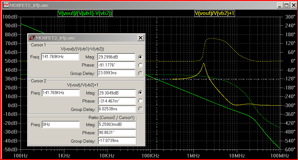
once the Cdom is reduced to speed up the loop with OK phase margin ~60 degrees – then just split the Cdom, add a R to (AC) gnd that puts the 2nd order pole/zero transition 5-10x lower in frequency than unity loop gain intercept
a little lead C across the feedback R tweaked the gain intercept response to look a bit nicer
and finally it is worthwhile to use a very small t_maxstep in a .tran for higher resolution distortion calculations - few 1000x smaller than your test frequency period
Bob's, Self's books are good – I've seen much of the info as it was developed, in JAES articles, articles, debates in EWW when it was a serious publication
and I've spent lots of time playing with sims of these simple audio amps – so I was able to just go with what I had seen work before
couldn't quickly find the BUZ parts so I used Bob's IRF Mosfet models – verticals may have more gain – definitely needed lots more bias V to get the current up to his recommendations – decreased gate stoppers – they shouldn't roll off loop gain – just be big enough to stabilize local parasitic RF oscillation
increased driver stage current, disconnected their bias R from output – gives better pull-down, less driver Q current variation
Bob uses very large input Q emitter degen R values – I prefer to have more loop gain so dropped his degen by 10x, doubled input stage current – more in line with Doug Self's book, examples
then started cutting the Cdom value while watching the “simple Middlebrook” Bode plot of V(vout)/V(a) – the 0 dB magnitude point on that curve is the loop gain intercept – phase margin is read from the cursor measurement box – past experience suggested Mosfet outputs could safely be used with loop gain intercept frequency of few MHz
once the Cdom is reduced to speed up the loop with OK phase margin ~60 degrees – then just split the Cdom, add a R to (AC) gnd that puts the 2nd order pole/zero transition 5-10x lower in frequency than unity loop gain intercept
a little lead C across the feedback R tweaked the gain intercept response to look a bit nicer
and finally it is worthwhile to use a very small t_maxstep in a .tran for higher resolution distortion calculations - few 1000x smaller than your test frequency period
Last edited:
Thank you very much for your support,
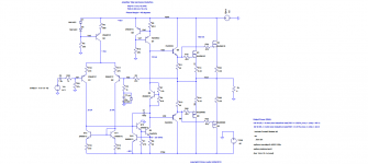
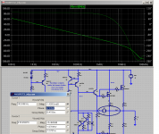
I've tried to start doing something similar, but I don't understand the two pole compensation, and when I reduce the degen resistors of the LTP open loop gain increases, and phase margin decreases, I don't know what to do, this amplifier I've made, uses IRFP verticals instead of BUZ laterals, but the problem is that I have in my stock lots of BUZs, but no IRFPs, I don't know why BUZs have such poor characteristics, when I bought them, and they are really expensive in my country, I thought they are good, it's safe to use 47 ohm gate stopper resistors for IRFPs, I've used 100 ohm, but I think that the minimum allowed to avoid oscillations is near 10 ohm. About your design seems just fine, but I've noticed a little peaking about 0.834 dB, but I think that's not a problem, right?
Attached my attempt to do something with lower THD 😛, your design, and the picture of the gain peak. Could you please put a mark on the graph showing how you do to check phase margin.
Thank you very much for your attention,
Best regards,
Daniel Almeida
Attachments
simple loop gain probe:
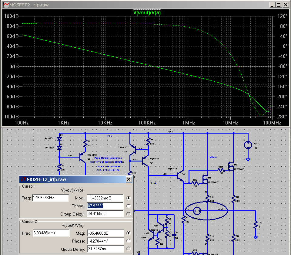
cursor 1 reading of V(vout)/V(a) gives phase margin, cursor 2 is at phase = 0 and gives the loop gain margin
phase margin of 60-90 degrees is "safe", "boring"
cursor 1 shows 0 dB loop gain intercept is near 150 kHz - a slow loop speed used back when big BJT could only manage 4 MHz ft
good layout, faster devcies, particualrly Mosfet can be used at loop gain intercept of 500 kHz to several MHz
phase margins of 30-45 degrees are "sporty" - can be used if you know a lot about the circuit, loads, interactions
phase margins below 90 degrees will show some closed loop peaking - I don't care about few dB at 100s of kHz - 20 kHz flatness is enough - you should add a few 100 kHz low pass filter on the input to reject RF anyway
the simple loop gain probe automatically measures just the excess loop gain
you can use your input AC measurement and some math to get "open loop gain" and the plot the feedback gain setting, ratio the 2 to get very similar numbers - within few %, few degrees:
Attachments

Last edited:
Hello jcx and thank you very much for your help,
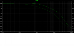
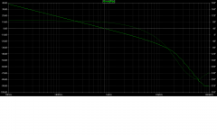
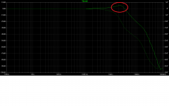
I've changed the CMiller capacitor from 150pF, which I think that is a terribly high value, and can have a very negative impact on the slew rate of the amplifier, to a 27pF capacitor and now I have a phase margin of more than 75 degrees and a large gain margin, I can lower the gain from 28 V/V to 11 V/V and the closed loop graph shows no signs of peaking (positive feedback) at step response, the phase margin with 11 V/V voltage gain is more than 60 degrees and gain margin is more than 12 dB. The problems are the remaining high THD levels at 20kHz which have a maximum of 0.03% for 4 ohm drive. THD1 is also high with a peak of 0.002% and typical values of 0.0007%. In the graph of the open loop gain of your amplifier there is a strange variation in phase, what is causing that. The open loop response can be seen plotting V(vout)/V(a) or as Bob Cordell said by putting an inductor connected between the output and the feedback resistor, and then applying a signal thru this point using a 1uF capacitor. Phase measure can be seen with 0 degrees as reference right.
Why in Bob Cordell's book the reference is -180 degrees and here we use 0 degrees?
Why we use open loop response (gain/phase) instead of closed loop response to evaluate phase/gain margin?
Using closed loop response all amplifiers seem to oscillate (phase reach more than 180 degrees at gains higher than 0 dB).
Why? The peakings are really dangerous as said Bob Cordell?
Peakings are caused by positive feedback and I think that positive feedback can make oscillations. Right?
The oscillations can destroy the amplifier?
PS: Without capacitor C6 in parallel with the feedback resistor the peaking that appears in the closed loop increases, is that normal?
Thank you very much for your attention,
Best regards,
Daniel Almeida
Attachments
-
 Phase_gain_cl_MOSFET2_irfp_27pF.png22.4 KB · Views: 51
 -
 Phase_gain_ol_MOSFET2_irfp_27pF.png36.7 KB · Views: 59
 -
 Phase_gain_cl_MOSFET21_irfp_2_pole.png24.1 KB · Views: 48
 -
 Phase_gain_ol_MOSFET21_irfp_2_pole.png25.7 KB · Views: 46
 -
MOSFET21.asc9.1 KB · Views: 48
-
MOSFET2_irfp.asc9.2 KB · Views: 51
-
Cordell Models.txt11.8 KB · Views: 49
Danny,
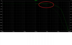
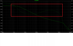
all 4 plots show an odd rippling from 20MHz to 100MHz?
I am wondering if you have the .trans set correctly.
The plot may be trying to show real ripples that are being suppressed by your settings.
Similarly plot3 should show a smoothly rising and falling peak. Yours is flat topped with "corners", odd?
Hi AndrewT,
What do you mean with flat topped with "corners"?
That seems a normal closed loop bandwith for a typical amplifier, I think, peakings are a sign of positive feedback, and you are saying that I should have peakings?
That's weird.
Best regards,
Daniel Almeida
What do you mean with flat topped with "corners"?
That seems a normal closed loop bandwith for a typical amplifier, I think, peakings are a sign of positive feedback, and you are saying that I should have peakings?
That's weird.
Best regards,
Daniel Almeida
5 minutes spare....
Had a quick play. This was only a quick mess around. 🙂
20Khz THD = 0.001%. ish for 1v input. PM = 66 deg.
That odd rippling is on my sims as well.
I don't like the transistor for stopping the VAS saturating. Prefer baker clamps.
Had a quick play. This was only a quick mess around. 🙂
20Khz THD = 0.001%. ish for 1v input. PM = 66 deg.
That odd rippling is on my sims as well.
I don't like the transistor for stopping the VAS saturating. Prefer baker clamps.
Attachments
Last edited:
Hi everyone,
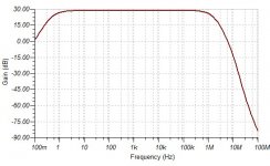
I've simulated the same amplifier using TINA from Texas Instruments.
Plots attached.
THD20 in TINA is much higher, why is that?
Best regards,
Daniel Almeida
I've simulated the same amplifier using TINA from Texas Instruments.
Plots attached.
THD20 in TINA is much higher, why is that?
Best regards,
Daniel Almeida
Thank you mcd99uk 😉
You added a Zobel network to prevent oscillations at the output stage, but I still don't understand two pole comp. My Miller dominant pole has some problem, why such high THDs with dominant pole, slew rate decrease?
Why did you connected the resistor of the two pole comp to the output instead of the ground? That brings any kind of improvement?
Without that transistor I can't use conventional protection systems, Q4 could be damage, right?
I forgot the attachements in my previous post, I'm sorry.
Best regards,
Daniel Almeida
Attachments
Last edited:
- Status
- Not open for further replies.
- Home
- Amplifiers
- Solid State
- Very high THD levels