Hello everyone,
Can anyone explain me how to pole compensation works, this type of compensation is much better for THD20, because it allows a much higher slew rate. Otherwise it seems less stable against oscillations, because two pole compensation creates peakings, the peakings are not allways harmful, but if at the frequency of the peaking the phase shift is 180 degrees or more, this means that the Barkhausen criterion for oscillation was met, right?
Why you use 2SCs instead of MJEs?
I'm not talking about your designs, in your designs, the's no oscillations, and they both have a good phase margin.
Best regards,
Daniel Almeida
Last edited:
feedback loop oscillation requires both 180 degrees phase shift and gain == 1 at the frequency of sustained oscillation
in common use of 2-pole compensation the phase dip doesn't go below 0 degrees phase margin - and that closest approach is when loop gain is high enough that "normal" range of load effects/loop gain variations won't reduce loop gain by the 20 dB or more required for loop gain == 1
the closed loop step response overshoot with 2-pole comensated isn't a direct indication of instability - or with other higher order compensation - which is why looking at loop gain with the various test circuits is valuable
Hi everyone,
I've tried to make a design with two pole compensation, this is stable?
It has a 60 degrees phase margin. I've used two pole compensation, connecting the resistor to the output instead of connecting it to ground, why some designers use one, and the others use another, what are the main advantages, disadvantages of both topologies. This amplifier has a maximum THD20 of 0.005% and a THD1 lower than 0.0002%.
Best regards,
Daniel Almeida
Attachments
you have to be perfectly satisfied with the AC gnd version of 2-pole Before connecting the R to the output in "TMC" - the stability has to be properly measured
the reduction in closed loop gain overshoot is exactly the problem I have with TMC's universal recommendation - the stability is still fully "2-pole" in complexity, reduced margins
in this case the (lack of) "closed loop overshoot doesn't directly indicate stability" goes the other way - possibly fooling some
Hello jcx and thank you very much for your support,
The problem is that I don't know what I should do to calculate the capacitors and the resistor, and about that design, it's fine, or will create some forms of instabillities?
Best regards,
Daniel Almeida
The problem is that I don't know what I should do to calculate the capacitors and the resistor, and about that design, it's fine, or will create some forms of instabillities?
Best regards,
Daniel Almeida
I'm no expert, in fact a beginner.
I have realised that simple miller comp always suffers results in higher THD compared with TMC and TPC. I found that TPC results in peaking of response and square wave overshoot. Which of course can be compensated for with a cap across the feed back resistor which again I prefer to avoid purely because I don't like the way the cap forms a perfect path for noise to get into the amplifier input. I prefer a good square wave response so err away from TPC.
I prefer 2sc transistors due to the fact they are faster and have lower cob. MJEs always seem to produce higher THDs. Mouser is a good source for these.
You could use a combination of TPC and TMC by having resistors to both GND and the amplifier output. It's an interesting concept and worth a play.
The complexities of miller comp is subject of much discussion as can be seem in the TMC vs TPC vs Pure cherry thread.
As you get into design you find yourself forming you own preferences. It's all about trade offs. There is no single answer to a problem.
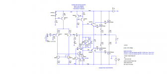
Attached is example TMC/TPC. I love this idea at least for results. Not analysed it much though. 0.0000583% THD 20K @ 1v input. PM = 82 (I think)
I have realised that simple miller comp always suffers results in higher THD compared with TMC and TPC. I found that TPC results in peaking of response and square wave overshoot. Which of course can be compensated for with a cap across the feed back resistor which again I prefer to avoid purely because I don't like the way the cap forms a perfect path for noise to get into the amplifier input. I prefer a good square wave response so err away from TPC.
I prefer 2sc transistors due to the fact they are faster and have lower cob. MJEs always seem to produce higher THDs. Mouser is a good source for these.
You could use a combination of TPC and TMC by having resistors to both GND and the amplifier output. It's an interesting concept and worth a play.
The complexities of miller comp is subject of much discussion as can be seem in the TMC vs TPC vs Pure cherry thread.
As you get into design you find yourself forming you own preferences. It's all about trade offs. There is no single answer to a problem.
Attached is example TMC/TPC. I love this idea at least for results. Not analysed it much though. 0.0000583% THD 20K @ 1v input. PM = 82 (I think)
Attachments
Last edited:
Yes, I agree with you mcd99uk, I think that TMC doesn't produce peakings in closed loop response, and overshoot in square wave transient analysis, TPC if not combined with the capacitor in parallel with the fb resistor can cause this problems (overshooting at 20 kHz square wave transient analysis. I've calculated the capacitors for TMC aprox 2*Cmiller (because the two TMC capacitors act a bit like Cmiller in series), and I've used 1kohm resistor, how the resistor is calculated?
Best regards,
Daniel Almeida
Best regards,
Daniel Almeida
- Status
- Not open for further replies.
- Home
- Amplifiers
- Solid State
- Very high THD levels