I looked at LLC resonant conversion.I have some articles on LLC SMPS to study
This is the current state of the art for SMPS because it permits ZCS/ZVS (Zero Current/Volt Switches to reduce losses and EMI).
Seemed like it could work for buck converters too but I am now less optimistic, I suspect there is some Non Minimum Phase behavior that will complicate feedback and probably
step response.
Whereas my intuition is that any PWM system will have hard commutation and consequent losses and EMI.
So maybe some kind of fly-back is worth a look, I believe there is "Boundary Mode" conduction that at least reduces turn-off EMI.
Otherwise it's back to linear class H, as recommended by several people.
David
Last edited:
Another approach would be running class ab amplifiers at reduced rail voltages during low volume levels. E.g. my av receiver switches to higher rail voltages if I select volume above -15db. Of course an amplifier only construction doesn't know when user selects high volume ... 😉
BR, Toni
BR, Toni
...my av receiver switches...if I select volume above -15db.
Thanks Toni, that is quite a clever idea, simple and yet I've never seen it.
What brand is the AV receiver?
Would not be too hard to send a control from the pre-amp.
Simpler than a switch mode down converter!
Best wishes
David
E.g. Denon flagships AV receivers with high number of output channels.
Running in "ECO mode". If you tune the volume above a specific db number you hear a relay switch click - I assume that this changes bias and/or rail voltages.
BR, Toni
Running in "ECO mode". If you tune the volume above a specific db number you hear a relay switch click - I assume that this changes bias and/or rail voltages.
BR, Toni
I assume that this changes bias and/or rail voltages.
BR, Toni
Rail voltage. Same in Marantz home movie amplifier, such as 7055 rails are switched between +/-38V, and +/-55V depending by the output power.
Sajti
Last edited:
...in "ECO mode". If you tune the volume above a specific db number you hear a relay switch click...
Kind of manual class H!
Often threads run off track with too many attempts to push alternative, "think outside the square" solutions.
But this one is actually pretty attractive, thanks.
Best wishes
David
Sajti, yes switched rails makes sense, was what I planned.
Last edited:
I looked at LLC resonant conversion.
This is the current state of the art for SMPS because it permits ZCS/ZVS (Zero Current/Volt Switches to reduce losses and EMI).
Seemed like it could work for buck converters too but I am now less optimistic, I suspect there is some Non Minimum Phase behavior that will complicate feedback and probably step response.
Whereas my intuition is that any PWM system will have hard commutation and consequent losses and EMI.
Finally had the time to return to this.
Best plan still seems to be to split the system into a central power supply and then buck down-converters to power individual amps.
This modular approach separates and encapsulates some of the issues.
The central power supply to handle soft-start, filter EMI noise from the mains input, line variation and safety isolation.
This can be SMPS, for which I have found some nice circuitry, or linear, to exploit the fact I have 3 phase power.
Then buck down converters just have to efficiently step the power down, with low EMI and reasonable efficiency.
Zero Volt Switched buck converter circuits would seem the obvious choice to achieve these objectives but, as usual, life is not so simple.
The ZVS seems to come with compromises in other areas, the MOSFET switches are stressed more by back EMF or the complexity is unpleasantly increased or the control becomes difficult - not just simple PWM.
If the Buck converters are too complicated then may as well just build a Class D amp and be done with it (as some people recommended in the first place😉.
So I have decided to start with a basic buck down-converter and just slow the transitions down -take a small hit on efficiency but reduce EMI.
And maybe a nice, simple ZVS circuit will occur to me as I work.
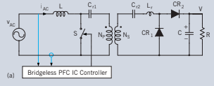
So here's the proposed SMPS front end, by Dr Cuk - anyone seen it?
Note that it runs off AC without the usual rectification to DC first but still works on both polarities 😱
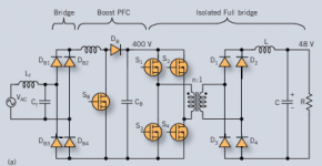
It replaces a conventional SMPS that usually looks like
So Cuk's circuit looks simpler but it's not exactly obvious how it can work, full explanation here.
PETarticles.pdf - Google Drive
David
Attachments
Last edited:
Are we moving into an area of more than 2 kW?
CRM PFC Control IC: TB6819AFG
Critical Conduction Mode (TB6819AFG)
・Suitable for power levels below 200 W
・Relatively simple circuit
Can you see scalable solutions?
IRAUDAMP9: 1.7 kW Mono, ±48 ~ 80V, Class D Amp
CRM PFC Control IC: TB6819AFG
Critical Conduction Mode (TB6819AFG)
・Suitable for power levels below 200 W
・Relatively simple circuit
Can you see scalable solutions?
IRAUDAMP9: 1.7 kW Mono, ±48 ~ 80V, Class D Amp
Last edited:
Something like this for the Chinese $ 50:
Conversion efficiency 90-96.7%
Rated power: 1000W
Peak power: 1500W
Input voltage: 200-240V
Output voltage: double DC70V.
Net weight: 450pcs
Size 156 * 100mm
Conversion efficiency 90-96.7%
Rated power: 1000W
Peak power: 1500W
Input voltage: 200-240V
Output voltage: double DC70V.
Net weight: 450pcs
Size 156 * 100mm
...more than 2 kW?
The central power supply could potentially drive -
Two sub woofers,
Front L,R and C
Surround L and R
Rear L and R.
So maybe 2 kW is overkill but does provide headroom for worst case.
CRM PFC Control IC: TB6819AFG
Critical Conduction Mode (TB6819AFG)
・Suitable for power levels below 200 W
・Relatively simple circuit
This is a conventional PFC circuit, did you look at the Cuk article?
The claim is that it supersedes this type of rectifier based PFC, eliminates diode loses and complexity.
It looks clever and Cuk is well credentialed.
But I haven't seen this idea used, maybe I have just missed it or maybe the idea is problematic.
Can you see scalable solutions?
IRAUDAMP9: 1.7 kW Mono, ±48 ~ 80V, Class D Amp
To use as a power supply?
I think Damir ("Dadod" used a class D amp to drive the rails of a linear amp.
...like this for the Chinese $ 50:
Conversion efficiency 90-96.7%
Rated power: 1000W
Peak power: 1500W...
Has the link been misplaced?
Best wishes
David
Last edited:
David: Has the link been misplaced?
- Forum rules do not allow. Look at Uncle Ali 🙂
There are also modules of amplifiers D 2 * 800 watts.
Ready-made modules are on sale for little money. The problem is correct integration.
You will need a control module (preamp) for this farm.
- Forum rules do not allow. Look at Uncle Ali 🙂
There are also modules of amplifiers D 2 * 800 watts.
Ready-made modules are on sale for little money. The problem is correct integration.
You will need a control module (preamp) for this farm.
Last edited:
To use as a power supply?
I think Damir ("Dadod" used a class D amp to drive the rails of a linear amp.
Best wishes
David
Hi Zen,
I have linear ClassA amp and ClassD amp ready to try, just occupied with other staff, but hope to test it this autumn, first tray.
Before that I tested ClassA + ClassB combination.
BR Damir
Best plan still seems to be
AD8066+THS4131 routed as intrumentation opamp for the input and first gain stage.
LT1016 as fast comparator, LMG1210 as half-bridge driver for pair of EPC2034 GaN FETs.
All wired in famous UcD topology at working freq like 1 MHz with a deadtime at 5-7 ns order.
Or just wait for Axign.
...All wired in famous UcD...
It is not clear to me exactly what you propose.
A Class D amplifier or a Class D inspired power supply?
It has occurred to me to use some kind of self oscillation control loop on a buck converter power supply.
Seems this could solve the control problem of how to maintain Zero Volt Transitions as the load varies.
There are a few patents for this but I haven't had time to study them carefully.
Class D amps and buck converters are quite similar, so a UcD style control system is an obvious idea to study.
Best wishes
David
...I have linear ClassA amp and ClassD amp ready to try...Before that I tested ClassA + ClassB combination.
Hi Damir
Hope you are well and that the new trials are successful.
Did you post the details of your plans or the Class-A + Class-B circuit?
I always like to see what you done and learn.
Best wishes
David
David: Has the link been misplaced?
- Forum rules do not allow. Look at Uncle Ali 🙂
There are also modules of amplifiers D 2 * 800 watts.
Ready-made modules are on sale for little money. The problem is correct integration.
You will need a control module (preamp) for this farm.
Until Trump banned Alibaba🙁
Hi Damir
Hope you are well and that the new trials are successful.
Did you post the details of your plans or the Class-A + Class-B circuit?
I always like to see what you done and learn.
Best wishes
David
Hi David,
ClassA + ClassB is just ClassA with ClassB efficiency (almost), it's not yet in a chassis, I'm expecting Connex SMPS to be delivered after some months waiting.
I used a layout similar to the 200W CFA and two pairs of output mosfets are working in ClassA and two pairs in ClassB.
BR Damir
ClassA + ClassB is just ClassA with ClassB efficiency (almost), it's not yet in a chassis...I used a layout similar to the 200W CFA...
I had a bit more think about this.
My plan was to have Buck down converters in each supply rail.
But a synchronous Buck Converter is practically a Class D amp.
So why have two Buck converters, why not just one?
That more or less reinvents the Class D + Linear Amp that you proposed a few years back.
Only issue is that the Linear amp power supply is floated, so the Class D must drive the stray capacitance.
I am wary of capacitive loads but it's probably not a serious problem.
Have you considered this issue?
Best wishes
David
A Class D amplifier or a Class D inspired power supply?
Hi, Dave!
Any, as you wish.
I suppose it's simpler to build such an UcD amp first, say at +-100 V supply rails. Then you can use such an amps as tracking supply for 'linear' amp.
Also keep in mind you need an adequate power supply, better LLC. Do not even try to use half-bridge or push-pull, those will equip you with a characteristic overtones.
Now there are a more efficient totem-pole PFC and appropriate controllers, even 3-phase.
TPH3208 TO-220 GaNs can be used at mains side.
Being LLC'ed your supply can be easily referenced to the output of 'linear' part and provide already 'tracked' rails.
But talking about DIYing i'ld prefer to use already accessible chineese LLC supplies, +-90 or +-110 Volts and 1-2 kWt rated.
So you need to just build fast GaN UcD modules and why not, stop at this.
But, really, before you continue, check this:
https://www.axign.nl/wp-content/uploads/AX5689_ProductBrief_v1.0.pdf
https://www.audioxpress.com/files/attachment/2659
I had a bit more think about this.
My plan was to have Buck down converters in each supply rail.
But a synchronous Buck Converter is practically a Class D amp.
So why have two Buck converters, why not just one?
That more or less reinvents the Class D + Linear Amp that you proposed a few years back.
Only issue is that the Linear amp power supply is floated, so the Class D must drive the stray capacitance.
I am wary of capacitive loads but it's probably not a serious problem.
Have you considered this issue?
Best wishes
David
I had to go back to my thread, it was quite time ago. I changed the ClassD amp look here https://www.diyaudio.com/forums/solid-state/304722-200w-class-amp-efficency-5.html#post5054156 to connect the feedback point after output inductor, but not tried it yet.
Only output mosfet power supply is floating, and I don't see the stray capacitance problem.
BR Damir
- Home
- Amplifiers
- Solid State
- Very Efficient Very Low Distortion Linear+ Amp