I'm designing a vented box for the Stryke/AE speakers AV12 which is a high excursion 12" driver with 23mm one way xmax. I'm trying to determine acceptable vent velocity. I've heard figures ranging from 5-10% of the speed of sound or 17 - 34 m/s, however, what is not clear is what is acceptable when the vents are flared. And there are flares and flares! A 10mm flare radius is not the same as 60mm!!
* what are your experiences with vents for high excursion drivers?
* has anyone done a vented box for this driver (AV12)?
* what vent velocity do you find acceptable for your ports and driver?
It would be good to have points of reference. For example:
"I used Tempest in a 200L vented box tuned to 22 Hz with a 5" vent with a 2" radius flare and simulations showed 33m/s max velocity in the vent but it wasn't a problem even for LFE use."
There's some info under Peerless engineering notes that it should be below 1/10 the velocity of sound, approx 35m/sec.
http://www.d-s-t.com/main/tech/appxls.htm
The main info I've found is that the flare opening at the edge of the box should be at least 1.5x greater than the port diameter and assymmetrical flares work better with a smaller flare on the inside than outside but extreme flared ports can be undesireable (B&W Flowport excluded of course).
Pass DIY Addict
Joined 2000
Paid Member
Hey Paul,
My sub used an Audiomobile MASS 12 driver (xmax of 20mm one way) in a 135L vented enclosure. The vent is 6" diameter PVC that is 36" long, providing an overall tuning of about 19Hz. The end of the vent is not flared and I have never detected any "chuff" or other obvious sign of vent turbulance at levels up to about 110dB in a room that measures 24x15x8 feet.
WinISD models the vent mach in the sub at about .07 Mach. Here is the web page write up the sub - the WinISD model is in the middle of the page.
Hope this helps.
Eric
Paul-
I use a jbl2226 on 175litres internal, and 33hz tuning with ~360cm^2 port area. With 240watts rms input, vent airspeed is ,<12.5m/s.
🙂
Keep it sealed until your sure that you wont get chuffing. Ofcourse you could tune it low like 20hz, and remember that music will not normally have that so no problem!(could even EQ it slightly down at tuning to prevent it) But then EQ ,you shouldnt need to.
EDIT: I did see somewhere that flare ports of twice the radius have can have 'double the airspeed' for the same chuffing level. Now I hope that is double radius,not diameter,etc. I forget where! Perhaps Isaac from subsim said it.
Eric, I was looking at the webpage with your sonosub. Do you think those fishes like sitting on top of the subwoofer enclosure when its pounding away? I bet they go nuts when it hits a low note. Back to the thread topic, flared ports can definately handle much higher velocity than non flared ports. The chuffing is a whistling caused by the air moving past a edge which creates small eddys. If the edges are more rounded, the eddys are not created as easily. Back in my newbie days (though i'm still a newbie compared to some) I made a vented box that had a airspeed of ~120m/s as calculated by winISD. The air velocity peaked there at 16hz and was plainly audible to say the least. I believe vent noise is not just a factor of airspeed in the vent however. Frequency also plays a large role. If you have an enclosure tuned at an easily audible frequency such as 30hz it will take much more air velocity to become audible chuffing than say 15hz where you cant actually hear the tone.
Thanks Rabbitz, I had a look at the Peerless note and it confirms 10% or mach 0.1. It seems this is what I should aim for and then add flares. Perhaps power compression is also an issue.
However, with this driver, a vented design means the driver won't go to its xmax. In fact excursion will be more like 16mm, short of its 23mm xmax. This could mean power compression is less of an issue. In which case I wonder if it is possible to design a smaller than optimum (according to the 10% rule) vent with good performance.
What is undesirable about extreme ports? (What do you call extreme?) In my case I'm thinking of 52 - 72mm radius flares for 100 - 120mm vents. This is 3 or 4 layers of 3/4" MDF.
What is it about asymetrical ports? I have heard just the opposite, that they should be symmetrical! I would think that it is the same as trying to achieve a symetrical magnetic field for driver motors. However, I have considered that the outside flare may be more critical as internal turbulence is most likely masked.
Eric,
Your driver is very similar to mine in output, slightly less xmax, although I may in fact be using less than you (impossible to get to xmax above tuning with a sane amount of power). I would think that a 6" vent could be replaced with a 5" flared vent.
Keep it sealed until your sure that you wont get chuffing. Ofcourse you could tune it low like 20hz, and remember that music will not normally have that so no problem!(could even EQ it slightly down at tuning to prevent it) But then EQ ,you shouldnt need to.
Mike, for music it would not be worthwhile, however I'm designing this for those bursts of LFE where there might not be anything to mask the sound. Also I plan to have them close to the listening position, so vent noise is critical.
EDIT: I did see somewhere that flare ports of twice the radius have can have 'double the airspeed' for the same chuffing level. Now I hope that is double radius,not diameter,etc. I forget where! Perhaps Isaac from subsim said it.
Don't you mean a flared port of half the area is acceptable? Hmmm, seems a bit unclear, will have to look into this ...
WinISD indicates that lower tuning lowers vent velocity. However, this means a longer vent. A larger diameter vent must be tuned higher to fit in the box.
If I go with a 120mm flared vent, I can get it to 880mm in my 60L box, hence tuned to 24 Hz. Peak velocity is 29m/s. If I use a 100mm vent of the same length it will be tuned to 20 Hz. This peaks at 19 Hz with 33m/s. Hence the bigger vent tuned higher is better from a turbulence point of view.
A passive radiator,would save minutes of your life due to not debating the different port options that arent optimal
🙂
🙂
Looking at SV subwoofers, it seems their top of the range sub B12plus uses 4 drivers very similar to AV12 (made by TC sounds, the cone, surround and magnet look identical). They use what appears to be one 4" precision port per driver. If I model this box with 2500 watts total input (from the recommended Crown K2), the vent velocity is quite high, unless a rumble filter is used. 20 Hz 6th order HPF gets vent velocity down below 29 m/s, but without this it goes above 40m/s.
While previously I had preferred lower rumble filters (Fc @ 16 Hz) due to their lesser impact on resonse around 20 Hz, it seems a higher fc helps a lot with vent noise.
While previously I had preferred lower rumble filters (Fc @ 16 Hz) due to their lesser impact on resonse around 20 Hz, it seems a higher fc helps a lot with vent noise.
mike.e said:A passive radiator,would save minutes of your life due to not debating the different port options that arent optimal
🙂
This is not a big ugly box sub! I'm working on an elegant curved design where the size and look are critical. Passive radiators are IMO a waste of money, force the use of a rectangular box and save only a small amount of volume (5-10L) while at the same time further compromising the stiffness of the box (due to the holes), hence requiring thicker walls and losing all of their benefits! They offer no improvement in performance!
Yet it would save time but if I were trying to save time, then I wouldn't be doing DIY!
Here's a few concepts I'm working on:
right
the clearance around the vent is deliberately less than it should normally be to extend the effective length. A local speaker builder tells me you can get 2 - 4 Hz lower Fb using this method with a downfiring vent. I have done this on both ends so they are symetrical. Not enough clearance around the internal vent, though. This option allows the largest possible vent diameter or the lowest possible tuning.
middle
same concept but only done on the internal vent. The interior should mask any turbulence caused by this technique, although the cone shaped piece should prevent this.
left
uses a larger 120mm vent - tuned higher ~24.5 Hz. A side benefit of this may be that there is some extra cooling. The vent is placed less than the diameter of the vent near the driver magnet, however this should have both a cooling effect and should if anything, lower the tuning. I'm concerned that placing the vent facing the driver may have some problems however:
* turbulence from the driver itself which would normally be masked
* will it couple to the box in a different way and not function correctly since it is facing the driver?
Dashed line shows the effective length.
Thoughts? Opinions on these approaches anyone?
Thanks to all who have commented so far 😉
Attachments
paulspencer said:Thanks Rabbitz, I had a look at the Peerless note and it confirms 10% or mach 0.1. It seems this is what I should aim for and then add flares. Perhaps power compression is also an issue.
However, with this driver, a vented design means the driver won't go to its xmax. In fact excursion will be more like 16mm, short of its 23mm xmax. This could mean power compression is less of an issue. In which case I wonder if it is possible to design a smaller than optimum (according to the 10% rule) vent with good performance.
What is undesirable about extreme ports? (What do you call extreme?) In my case I'm thinking of 52 - 72mm radius flares for 100 - 120mm vents. This is 3 or 4 layers of 3/4" MDF.
What is it about asymetrical ports? I have heard just the opposite, that they should be symmetrical! I would think that it is the same as trying to achieve a symetrical magnetic field for driver motors. However, I have considered that the outside flare may be more critical as internal turbulence is most likely masked.
Hi Paul
I call any radius on the flare which is more than the radius of the port extreme as at the outlet it would be more than twice the diameter of the port. These would show more compression and distortion at higher SPL's. Asymmetrical ports with smaller radius on the inside are supposed to be better at reducing distortion and compression.
There was some work done by some guys as JBL and Infinity, preprint 4855 from 105th AES convention 1998 on ports (no I don't have a copy but someone around here might and you can get it from their website if you pay for it).
When it's all said and done, to reduce chuffing etc, the only way is to increase the port diameter and flared port can help greatly and I've seen stuff around like a 3" flared is like a 4" straight port. There is some formulae on diysubwoofers but it relates only to if you have no, 1, 2 flares on the port.
I've posted this before but the B&W flowport I use should chuff like mad but doesn't and it's only 65mm for a Peerless 10" XLS. The flare radius looks bigger than it actually is as they use an involute curve so the further out go go it's more like a taper than a radius.
Attachments
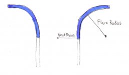
you know I really wonder if all those little depressions they put on that flowport really help that much. I think there is some bit of confusion about what you meant by radius on the flare rabbitz. I think I understand though, and I have drawn a little picture so you can tell me if I'm right. flare radius could only describe flares that are circular arcs and not some conic or perhaps a shape that isnt defined by a simple mathmatical function. End correction for different flares is surely different.
Attachments
BA,
B&W have info on their site in their tech development section, quite interesting. It's very much like golf balls. I don't think it is a gimick. As I understand, it creates very small eddies that introduce a boundary layer of moving air on the edges - I think it is the acoustic/aerodynamic equivalent of sliding down a wet slippery slide vs bare skin on dry hot rubber! OUTCH!
This makes the air follow the shape of the flare better, helping it overcome the inertia where it wants to move straight out the vent, which creates turbulence between the rapidly moving and the stagnant air.
This diagram shows the idea
Attachments
Supposing a port were not a simple radius. If we define it by two vectors instead, one parallel and one perpundicula to the direction of the vent, which should be bigger. I would say it might be an advantage to make port flares so that they extend further along papallel to the direction of the port, as this goes with the inertia of the moving air.
With standard flares of a given radius, or close to it, like the Precision ports, it seems you can take the effective length to go up to half of the length of the flare. This may change with different flare shapes.
With standard flares of a given radius, or close to it, like the Precision ports, it seems you can take the effective length to go up to half of the length of the flare. This may change with different flare shapes.
paulspencer said:BA,
B&W... <snip> ...very much like golf balls. <snip>
This diagram shows the idea
Golfers a long time ago noticed that the older and more beat-up their balls were the longer they would fly. The physicists got ahold of this and now golf balls are all dimpled for good reason: reduced drag. The air has a harder time holding on to the dimples. This would probably get you better fuel economy in your car, but who would buy a golf-ball looking car?

Anyhow, for reducing surface tension of air to a solid surface, the concept is pretty good.
I plan to try this on my vents ... should be interesting. The difficulty is doing a quick AB test as I'd have to make two the same with only the dimples on one of them.
BUMP! ... no comments on the three designs anyone?
BUMP! ... no comments on the three designs anyone?
Paul
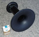
This will give you a better idea of the dimples which are 4mm dia x 2mm deep. The ones near the port tube are smaller. It would be easy to make the dimples in MDF but the layout is not so easy plus heaps of time. The inside flare is also dimpled BTW, but heaps less a smaller. Here's a pic to show you a bit more detail.
This will give you a better idea of the dimples which are 4mm dia x 2mm deep. The ones near the port tube are smaller. It would be easy to make the dimples in MDF but the layout is not so easy plus heaps of time. The inside flare is also dimpled BTW, but heaps less a smaller. Here's a pic to show you a bit more detail.
Attachments
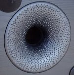
What is the diameter of that flare at the largest? What is the diam of the smaller dimples? I didn't think they would be that big!
The port flare is 230mm outside diameter....... yes 230mm for a 65mm port. The smallest dimples are 2.5mm x 1.25mm deep.
To give you some idea on the value of this thing is that it's for a Peerless 10" XLS, Vb=35 litres, Fb=29Hz.
This port is 65mm dia x 253 long which should give a port velocity of 90m/sec at 200W and 65m/sec at 100W so it should chuff and bang like crazy but the sucker doesn't.
To get a port with acceptable velocity of less than say 30m/sec, I would need 115mm dia x 893 long with a port velocity of 30m/sec at 200W and 22m/sec at 100W.
So there is definitely something happening with this port.
Here's a profile with the port starting at 32.5mm R, slight taper up to point 1, 65mm R (same as port dia) to point 2, then a taper with a slight curve up to the end. The distance across the top is 115mm and the height from the port to the flare in the vertical is 65mm. So the radius and the height is the same as the port dia. How much is cosmetics and how much is for sound.....dunno. BTW, this is for a downfiring port.
The inside flare has a dia of 110mm and looks like a stock part from the 7 series B&W's.
Hope this info helps.
Attachments

- Status
- Not open for further replies.
- Home
- Loudspeakers
- Subwoofers
- vent turbulence and high excursion drivers