
Pin compatible is the G6H-5V from Takamisawa and available at Conrad, stock# 50 47 00-06 at 5,60€ p/p.
Regards
Regards
I'm a little at my patience's end....
I can not get the voltage doubler to work properly....
I have a small traffo which is marked 2 x 22V, unloaded it measures closer to 26VAC, connecting the secondaries in series gives me 51VAC... when I connect this to the voltage doubler I get about 300VAC from rail to rail, with only one secondary connected I am getting 77VAC per rail (155V rail to rail)...
What did I miss? why no work? will make tube go boom?
EDIT:
Just had the thought to actualy measure DC... whell it still gives about 70VDC per rail.... is that ok?
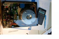
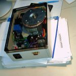
I think this is the last thing, apart from refinishng the case, that needs sorting out... I had to make custom PCB's to fit everything in the amp's case (refurbishing) also the buffer is teamed up with a lm3886 in inverted config (courtesy of digi's pcb's - ya sorry I copied it with mah evil coki pen....)
Also is a 25second delay softstart enough? thats more or less what I get from my relay... Modification of the circuit includes 2 pilot lights which shows warmup and active status, by wiring 240V pilot lights to the dpdt relay. Input selector and LED display is done, and I believe the VU meter section should work, as I relaced all opamps and transistors on it... (acctualy I still need to figure out a powersource for it, but we are at 3 transformers allready....
I can not get the voltage doubler to work properly....
I have a small traffo which is marked 2 x 22V, unloaded it measures closer to 26VAC, connecting the secondaries in series gives me 51VAC... when I connect this to the voltage doubler I get about 300VAC from rail to rail, with only one secondary connected I am getting 77VAC per rail (155V rail to rail)...
What did I miss? why no work? will make tube go boom?
EDIT:
Just had the thought to actualy measure DC... whell it still gives about 70VDC per rail.... is that ok?
I think this is the last thing, apart from refinishng the case, that needs sorting out... I had to make custom PCB's to fit everything in the amp's case (refurbishing) also the buffer is teamed up with a lm3886 in inverted config (courtesy of digi's pcb's - ya sorry I copied it with mah evil coki pen....)
Also is a 25second delay softstart enough? thats more or less what I get from my relay... Modification of the circuit includes 2 pilot lights which shows warmup and active status, by wiring 240V pilot lights to the dpdt relay. Input selector and LED display is done, and I believe the VU meter section should work, as I relaced all opamps and transistors on it... (acctualy I still need to figure out a powersource for it, but we are at 3 transformers allready....
Hi Wim
Looks good so far. I'm curious how the amp testing will progress.
About my board: hmmm....., I binned the project to be honest.
Mainly because of the lack of intrest and secondly because I first want to finish all the rest I've got going on.
Regards
Looks good so far. I'm curious how the amp testing will progress.
About my board: hmmm....., I binned the project to be honest.
Mainly because of the lack of intrest and secondly because I first want to finish all the rest I've got going on.
Regards
You are right GeWa, the overall interest in this subject is very low.
Succes with "the rest" of your projects.
Succes with "the rest" of your projects.
Mine is just about done, takeing a break from the soldering for a few minutes... as I noticed a few mistakes, must be getting tired..
Nordic said:
EDIT:
Just had the thought to actualy measure DC... whell it still gives about 70VDC per rail.... is that ok?
.......
Also is a 25second delay softstart enough? thats more or less what I get from my relay... Modification of the circuit includes 2 pilot lights which shows warmup and active status, by wiring 240V pilot lights to the dpdt relay. Input selector and LED display is done, and I believe the VU meter section should work, as I relaced all opamps and transistors on it... (acctualy I still need to figure out a powersource for it, but we are at 3 transformers allready....
Hi,
provided your caps can take it +/- 70V are fine.
Also 25 sec should be enough to let the tube warm.
I have mine waiting to be encased but I've been delayed by my Aikido preamp (after all I already have a Amp3 and 2 My_Refs, so I wasn't so in a hurry).
Cheers
Andrea
Lol, wel I started on the 13th of Dec, and I'm only finishing now...
Cant wait to have easy source selection again.... 🙂
Caps are all 100V, I'm sure the rails will drop a bit under load, the 70V is what I get straight from the PSU with nothing connected...
Getting everythng in the case looked so easy at first, but its a nightmare... I'm pretty worried about my ground stars etc...as I was a bit ambitious in adding features, but I will cross that bridge when i get there...
hello all,thanks for your unremitting tryout🙂
I am going to arrange a customize kit now,it will include all hard to buy parts.
I have do a remodify of the old board,still no idea if go with GeWa or mine.when the new board will available soon and will be combo offered with the kit.
thanks again,
Zang
I am going to arrange a customize kit now,it will include all hard to buy parts.
I have do a remodify of the old board,still no idea if go with GeWa or mine.when the new board will available soon and will be combo offered with the kit.
thanks again,
Zang
GeWa said:Made a few small changes. I think I've covered everything now.
http://www.diyaudio.com/forums/showthread.php?postid=823859#post823859
Regards
Nice!Just a once-over,I think the board should leave more romm for the terminal.remove the pot make the layout clean is a good idea.for save the sound,I don't like the small relay in sginal route.
best
LJ
I also think the old version's PSU with the relay on the AC wires to the amp's tranny was more elegant.
Also I would prefer the chips to be side by side, as opposed to on oposite sides of the board... this forces you to get a case of just the correct width, I think the traditional way of using a long heatsink with 2 chips on would be much more adaptable to custom designs.
Also I would prefer the chips to be side by side, as opposed to on oposite sides of the board... this forces you to get a case of just the correct width, I think the traditional way of using a long heatsink with 2 chips on would be much more adaptable to custom designs.
^&%&*, just broke a trace on the buffer pcb, can I suggest you making the pads a bit more substantial....
Got spare pcb, somewhere that I made as my first PCB ever... just got to take a break again...
And to think it was the very last thing to be connected... Murphey I tell you.
Got spare pcb, somewhere that I made as my first PCB ever... just got to take a break again...
And to think it was the very last thing to be connected... Murphey I tell you.
Be careful with soldering...
IMHO a relay that shunts the signal can't hurt that much (during operation it is open); BTW in my amp I used the relay to switch the primary of the power trafo (to limit contact damage due to inrush current)
Cheers
Andrea
IMHO a relay that shunts the signal can't hurt that much (during operation it is open); BTW in my amp I used the relay to switch the primary of the power trafo (to limit contact damage due to inrush current)
Cheers
Andrea
Oh the frustration!
The 6.3V heater lines only give 3.8V when I actualy have the tube in there... this also causes the relay not to switch the amp part on...
If I pull out the tube the pins measure 6.3V and the relay swithces...
It is powered by a 7.2VAC 1.5VA transformer... only other things on the thransformer is 2 leds, the NE555 and a 5V relay.
Apart from this I should be done.
Need help... close to tears now. 😕
Nordic said:Oh the frustration!
The 6.3V heater lines only give 3.8V when I actualy have the tube in there... this also causes the relay not to switch the amp part on...
If I pull out the tube the pins measure 6.3V and the relay swithces...
It is powered by a 7.2VAC 1.5VA transformer... only other things on the thransformer is 2 leds, the NE555 and a 5V relay.
Apart from this I should be done.
Need help... close to tears now. 😕
Your trafo is way too small. 1.5 VA is close to nothing.... especially if you want to regulate.
You'd better use at least a >10VA trafo (the filament asks for about 300-350mA, plus you have the regulation losses and the relay consumption).
Cheers
Andrea
Expletive....!!!!!!!!!!!!!!!!!!
Ok I see, and I remember the rating on the transformer was something like 0.1A which I though would be enough..
All I have in the meantime is a 6VAC traffo rated for 1amp (6 va?)
and a 2x12VAC traffo rated 1.5VA.. guess we'll have to wait till Monday then before we hear the results, as I'm leaving early on Saturday to go visit my grandma
- Status
- Not open for further replies.
- Home
- Amplifiers
- Chip Amps
- VBITNGC building & comment