Sir_John said:
1. For High current (HC) we need a transformer with 2x25 V AC secondaries, VA rating undefined. Please define the VA rating.
2. For Low Current (LC) we need a transformer with a secondary 1x 45 V AC or 2x 22V AC connected in series. Again I cannot find how big the transformer should be. Please define VA rating.
3. For delay circuit and heating of the tube we need a transformer with 7V AC secondary which should be small. Ok. How small. Again, VA=?
Also, in the schematic published there:
http://taihu.bjtzh.gov.cn/~digi01/VBITNGC- Files/VBITNGC_SCH.gif
It is not clear what is the value of the F1 fuse?
It is also not clear 100% to me what are K1 and S1 and S2 in this schematic.
Hi there,
I'm no expert either, but I'll give some feedback since it seems very few are interested in valve buffered chip amps these days. (There was a flurry of interest a year or two ago but it seems to have cooled now.) I'm not building Franz's and digi's amp, but a similar one, point to point construction.
Some of my observations:
1) HC transformer (to supply the chips): There is a lot of information on this chip amp forum about what VA rating to use for the amp. Just do a search. I'm using 300VA (it might be over-kill, but I my theory is to have as much in reserve as possible here!) I would say to use a minimum of 160VA for the chips if using one transformer for both channels.
2) LC transformer (to supply the tube): I'm using lower voltage at present. 30VA 2x25V transformer. I would say that this is the minimum.
3) Tube filament and start-up delay transformer: Absolute minimum would be 5VA for the filament only. I'm powering the filament and start-up delay by using a 15VA 9V transformer with a regulated supply. With this VA rating I have 6.5V supply before the delay relay turns on, then when the relay is on the voltage sags to the recommended 6.3V for the tube filament. Thus I would say that 15VA rating in this application is fine.
Fuse F1 - Maybe someone else can help you here?
K1 in digi's schematic is the start-up delay relay. S1 and S2 are the two "sides" to the relay, each side switching the signal to each amp chip to the ground.
Forum member Nuuk has a website that you may find very helpful, here:
http://myweb.tiscali.co.uk/nuukspot/decdun/gaincloneindex.html#top1
Happy building
 🙂
🙂PS: My wife is also from Belgrade - but just don't ask me to speak Serbian

Very well explaned falcott, you just beat me to the answers.
I'm using the exact same transformers as you.
Regarding the fuse: I first want to measure how much current it draws before I can answer this.
This is indeed a very slow and silent thread 🙁
Regards
I'm using the exact same transformers as you.
Regarding the fuse: I first want to measure how much current it draws before I can answer this.
This is indeed a very slow and silent thread 🙁
Regards
Thank you falcott, gewa.
Gewa, I am looking forward to see results of your F1 measurements.
And yes, falcott, best regrds to your wife, lucky you for having one Belgrade lady to be your better half.
Srdjan
Gewa, I am looking forward to see results of your F1 measurements.
And yes, falcott, best regrds to your wife, lucky you for having one Belgrade lady to be your better half.
Srdjan
Digi01,
Could we have the Eagle files for PCB DIY etching/milling please? Don't deny it and say that it's not Eagle. I can recognize that schematic image format and layout anywhere. 😀
If it is only purchasable, then thats okay. I just asked because I'm in the US and shipping from over oceans can be expensive. 🙁
DJ Exprice said:Digi01,
Could we have the Eagle files for PCB DIY etching/milling please? Don't deny it and say that it's not Eagle. I can recognize that schematic image format and layout anywhere. 😀
If it is only purchasable, then thats okay. I just asked because I'm in the US and shipping from over oceans can be expensive. 🙁
I hate to burst your bubble but that PCB is NOT designed in Eagle!
Believe me, I know that for a fact.Regards
Huh? Then where did this come from?
http://taihu.bjtzh.gov.cn/~digi01/VBITNGC- Files/VBITNGC_SCH.gif
^I know that this schematic image is Eagle though^
If anyone can find this .sch file, they rule and they saved about 500 people from doing it by hand and being 🙁 that they had to.
Thanks! 😀
http://taihu.bjtzh.gov.cn/~digi01/VBITNGC- Files/VBITNGC_SCH.gif
^I know that this schematic image is Eagle though^
If anyone can find this .sch file, they rule and they saved about 500 people from doing it by hand and being 🙁 that they had to.
Thanks! 😀
This is indeed a very slow and silent thread
Of course: owners of a VBITNGC are busy listening good music in good quality 😀
About the F1 fuse: 50mA is O.K.
BTW: it is recommended to add fuses on the primary side of the high current tranny (try what you need for the inrush current, 3A/230V slow or more) and the filament tranny (100mA at 230V).
Kind regards
Franz
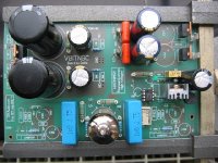
Very nice work Loek. You won't believe it, but i use exactly the same relais and 2W resistors as you! unbelievable.
exactly the same relais
Hi Wim, indeed unbelievable, but i know a very nice supplier in the neighbourhood.
I connected the transformer for the heatingsupply, C20 is 1uF poly, R9 is 120 ohm and adjusted the output to 6,3 V.
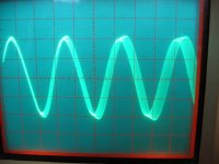
It works! I placed the tube and inspected the voltage with a scope and found that the regulator is oscillating.
So i removed the 1uF and placed a 10uF elco: clean picture.
Display 100mV and 1uSec/div.
That are my findings.
Loek
Hi Wim, indeed unbelievable, but i know a very nice supplier in the neighbourhood.
I connected the transformer for the heatingsupply, C20 is 1uF poly, R9 is 120 ohm and adjusted the output to 6,3 V.
It works! I placed the tube and inspected the voltage with a scope and found that the regulator is oscillating.
So i removed the 1uF and placed a 10uF elco: clean picture.
Display 100mV and 1uSec/div.
That are my findings.
Loek
Attachments

Do LEDs introduce noise?
In this situation, driven by the filament/relay voltage: No!
Franz
Re: LED
Good point Loek,
I shall measure my relais voltage too, and adjust it
if necessary.
What i found in this design and also in the previous design (from Digi and Franz), is that turning the pot that increase or decrease the delaytime of the relais is not working properly; whatever the position of the pot is, the time stays the same (about 25 seconds). For me its perfect, but why does't work this pot? What is your experience Loek, or someone else?
I have the VBITNGC working, and the first experiences are good. When time comes i will connect it to my regular audio system. I will report the results. I have the earlyer system (Digi and Franz) playing for about 9 months, ans i like the sound!
Succes building and playing to all of you!
loek said:I found that my relay voltage was a little high: 8,5V for a 5V type so i added a LED in series with the relais.
Nice red if the circuit is on...
Good point Loek,
I shall measure my relais voltage too, and adjust it
if necessary.
What i found in this design and also in the previous design (from Digi and Franz), is that turning the pot that increase or decrease the delaytime of the relais is not working properly; whatever the position of the pot is, the time stays the same (about 25 seconds). For me its perfect, but why does't work this pot? What is your experience Loek, or someone else?
I have the VBITNGC working, and the first experiences are good. When time comes i will connect it to my regular audio system. I will report the results. I have the earlyer system (Digi and Franz) playing for about 9 months, ans i like the sound!
Succes building and playing to all of you!
whatever the position of the pot is
Hi Wim, i did not have a pot that size yet so i used a 47k resistor and with C17=100uF the delay is 30 seconds. so i keep it this way.
I can short the 47 k and count...
edit:
Did it and then it is 25 seconds, so it works as it would be...
Loek
Hi Wim, i did not have a pot that size yet so i used a 47k resistor and with C17=100uF the delay is 30 seconds. so i keep it this way.
I can short the 47 k and count...
edit:
Did it and then it is 25 seconds, so it works as it would be...
Loek
Re: exactly the same relais
This is very interesting. Have anyone else who finished this amp found this or something else? Actually, who has it really finished? Franz? Digi? GeWa? If you guys finished it, post some jpegs here!
loek said:Hi Wim, indeed unbelievable, but i know a very nice supplier in the neighbourhood.
I connected the transformer for the heatingsupply, C20 is 1uF poly, R9 is 120 ohm and adjusted the output to 6,3 V.
It works! I placed the tube and inspected the voltage with a scope and found that the regulator is oscillating.
So i removed the 1uF and placed a 10uF elco: clean picture.
Display 100mV and 1uSec/div.
That are my findings.
Loek
This is very interesting. Have anyone else who finished this amp found this or something else? Actually, who has it really finished? Franz? Digi? GeWa? If you guys finished it, post some jpegs here!
There is another strange thing i found with this design (the first desing from Franz and Digi and the second design too): With no source connected there is a loud brrrrrrrr in the speakers. When i connect a source (CD-player) there is no brrrrrrr. I can live with it, but is is strange.
Anyone figured out where the schematic file is? 😀
(I don't mean to sound annoying...but I really want to make one of these because I think that they will sound amazing!)
(I don't mean to sound annoying...but I really want to make one of these because I think that they will sound amazing!)
Anyone figured out where the schematic file is?
Not so difficult if you check the last posts: post 420.
Wim, normally there has to be a resistor from grid to ground.
If you leave the input open there is no "leaking resistor " for the grid.
You can connect a resistor (1Meg) parr. to the inputconnector.
Maybe this will help.
good luck, Loek
Not so difficult if you check the last posts: post 420.
Wim, normally there has to be a resistor from grid to ground.
If you leave the input open there is no "leaking resistor " for the grid.
You can connect a resistor (1Meg) parr. to the inputconnector.
Maybe this will help.
good luck, Loek
- Status
- Not open for further replies.
- Home
- Amplifiers
- Chip Amps
- VBITNGC building & comment