Member
Joined 2002
digi01 said:I think it is preferable to ground the input pin.
FYI,here is a overall walkthrough of VBITNGC by Gewa.LINK
Zang
I like this board. Who sells it ?
digi01 said:I think it is preferable to ground the input pin.
Zang
Thanks for that, Zang. But for what reason do you consider this method best?
The idea of shorting a valve preamp or buffer output is to protect the following stages while the valve stage 'settles down' as it warms up.
I never had a problem with my VBIGC but it is better to be safe than sorry.
I certainly short the output of my valve pre amp to avoid damage to any power amp that is connected after it. The delay I use is around a minute to be on the safe side.
I never had a problem with my VBIGC but it is better to be safe than sorry.
I certainly short the output of my valve pre amp to avoid damage to any power amp that is connected after it. The delay I use is around a minute to be on the safe side.
Nuuk said:The idea of shorting a valve preamp or buffer output is to protect the following stages while the valve stage 'settles down' as it warms up.
I never had a problem with my VBIGC but it is better to be safe than sorry.
I certainly short the output of my valve pre amp to avoid damage to any power amp that is connected after it. The delay I use is around a minute to be on the safe side.
Thanks. 🙂
So would a 10k resistor to ground be ok? Or more?
I actually short the output to ground with a direct connection! I checked that this was OK before doing it and I have had no problems, even shorting the valve pre-amp for a whole minute! 😉
just to set you at ease... I use the relay to switch the amp's transformer (hybrid vbitngc).. with no ill effects after nearly a year so far...
falcott said:
Thanks. 🙂
So would a 10k resistor to ground be ok? Or more?
10k is too big.consider lots of pre amp under 1OHM output resistence so direct short is ok.
Zang
Direct shorts make me nervous though...
Me too but I a couple of very trusted contacts confirmed this would be OK before I tried it! 😉
Its no diffirent from turning a perfect pot to 0 output, isn't it...?
Or 0V 0mA input. In the presence of live power rails, nothing over the input = an incomplete circuit. A dead short on the input is the closest thing you can get to a signal source of 0 voltage and current.
Or 0V 0mA input. In the presence of live power rails, nothing over the input = an incomplete circuit. A dead short on the input is the closest thing you can get to a signal source of 0 voltage and current.
Transformer specifications
Hello everyone. I am so glad to see that this thread is up and running again.
Can any of the designers tell us exact specs for the transformers, voltages and VA ratings, thanks.
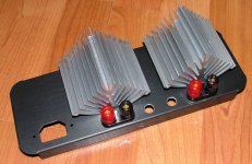
Also, I am not sure that I read here any actual listening impressions as well as images of the finished amp. Is there any of a kind?
My amp is in "almost ready to begin assembly stage".
Best to all,
Srdjan
Hello everyone. I am so glad to see that this thread is up and running again.
Can any of the designers tell us exact specs for the transformers, voltages and VA ratings, thanks.
Also, I am not sure that I read here any actual listening impressions as well as images of the finished amp. Is there any of a kind?
My amp is in "almost ready to begin assembly stage".
Best to all,
Srdjan
Allthough it will never be competition for good valve gear,it sounds pretty good, I have used my valve board with inverted GC, NIGC, and My_ref C. I find the top end slightly less sparkling, which is not altogether a bad thing with chip amps. This is most likely due to the ecc88 I settled on. It does make CD's sound a bit nicer then when played straight. Also makes bass sound a bit more firm, not boomy though. I'm considering trying 6N1-P and maybe E88CC later on. I skimped on transformers something fierce, yet it is still working awesomely after a year...
from memory I used a 2 x 24V 56va PCB mount tranformer for the voltage doubler and an even smaller 9V transformer regulated to 6.3V. At 6.3V x 0.365A the heater needs only about 2.3VA of power, obviously due to system losses (heat) and other inefficiencies, you will likely need double or 4 times this rateing...
from memory I used a 2 x 24V 56va PCB mount tranformer for the voltage doubler and an even smaller 9V transformer regulated to 6.3V. At 6.3V x 0.365A the heater needs only about 2.3VA of power, obviously due to system losses (heat) and other inefficiencies, you will likely need double or 4 times this rateing...
Sir_John
You will find all the necessary info on digi01's webpage of the VBITNGC.
http://taihu.bjtzh.gov.cn/~digi01/VBITNGC.htm
Regards
You will find all the necessary info on digi01's webpage of the VBITNGC.
http://taihu.bjtzh.gov.cn/~digi01/VBITNGC.htm
Regards
Walter,
I am not very experienced builder, so I would like to make things as much clear as possible. Better save than sorry. I've examined digi's page and didn't find all the data. Correct me if I am wrong please.
So here are things I am not certain about:
1. For High current (HC) we need a transformer with 2x25 V AC secondaries, VA rating undefined. Please define the VA rating.
2. For Low Current (LC) we need a transformer with a secondary 1x 45 V AC or 2x 22V AC connected in series. Again I cannot find how big the transformer should be. Please define VA rating.
3. For delay circuit and heating of the tube we need a transformer with 7V AC secondary which should be small. Ok. How small. Again, VA=?
Also, in the schematic published there:
http://taihu.bjtzh.gov.cn/~digi01/VBITNGC- Files/VBITNGC_SCH.gif
It is not clear what is the value of the F1 fuse?
It is also not clear 100% to me what are K1 and S1 and S2 in this schematic.
If you or anyone else can help making those things clear, I would be grateful. Thanks.
Nordic:
I got one Philips miniwatt E88CC tube for this amp. When It is finished, I'll let everyone know how this combination sounds. I also intend to try one russian military grade tube. We shall see the outcome. Thanks for your response.
Regards,
Sir John
- Status
- Not open for further replies.
- Home
- Amplifiers
- Chip Amps
- VBITNGC building & comment