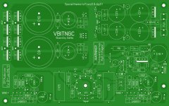
This is the final version now!
I've been checking the layout a few time now to make sure there were no screw ups and guess what......., there was one.
I took care of it and made a few small last minute adjustments.
Also been talking behind the scene with digi01 to get the boards made. Looks promising but for the moment he's a bit short on time so, be patient.
Regards
Attachments
Nice board GeWa!.
I have a strange problem starting up my amp. When i connect the psu, there seem not to be any problem. The tube glows up, the voltages are good an without connecting a source and a load i measure the next values:
DC offset left is 45 mV, DC offset right is 90 mV. Seems to be good too.
resistance left input is 46 kOhm, right input is 44 kOhm. Resistance output left is 18 kOhm, output right is 18 kOhm.
Looks not bad to me.
Now at the moment i connect a source (signal generator, 1 kHz sinus, 0,8 mV) the lights go out. On nthe distributiopanel of my house the fuse did not go out, but the earth securety switch (i do not know how to translate, but in Holland it is common to detect a current between the earth and the zero).
I can not see any strange on the amp boards, besides that the high voltage connections (+ 60VDC and -60VDC are connected on the amp, but NOT the gnd of the high voltage. In the schematics there is no information about how to connect this high voltage gnd, and one of the patches is to make a connection on the PSU board between the high voltage gnd and the high current gnd, so there seems to be no need to connect the hhig voltagegnd to the ampboard.
Do anybody can help?

If you like a plain GC, you'll like this better... not sure I'm a fan of the T-network, but I have teamed the valve part to my regular rev C, and it is gainclone heaven.
The T-network can sound a bit clinical - though the detail is definitely up. Personally I think there are better unity gain buffers available, namely the transistor ones published on NUUKs gainclone site, having heard these and the basic valve buffer outlined here - I don't think the valve buffer is worth the extra effort. Of course other may disagree strongly.
Shoog
Shoog
"Hi Shoog,
how does compare the transistor buffer to your JLTI-like tube buffer?
Cheers"
Its so long ago since I actually had that configuration that I would be hard pressed to say with any accuracy. I still use a Gainclone on my computer with the bipolar transistor buffer. It sounds lovely and warm. Sticking my head out I would say that in the context of the Gainclone, it comes very closes to the JLTI-valve buffer, and the saving in hassle is enormous.
Shoog
Very nice Digi01. Is the board availebel for intrested peaople like me? If so, how to pay ?
Thanks.
Thanks.
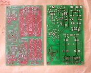
Looks good Zang 🙂
It's weird to see these in reality now. I've seen the layout for so many hours on my screen, but still.....
I do hope that they are bug free and that everybody can finish the amp without troubles.
Regards
It's weird to see these in reality now. I've seen the layout for so many hours on my screen, but still.....
I do hope that they are bug free and that everybody can finish the amp without troubles.
Regards
GeWa said:Looks good Zang 🙂
It's weird to see these in reality now. I've seen the layout for so many hours on my screen, but still.....
I do hope that they are bug free and that everybody can finish the amp without troubles.
Regards
How about a parts list and the enclosure part # again?
How many people have requested boards, and is anyone still interested in a parts GB?
I will not be doing it, I have a friend who helped me with the final kitting of the Krell GB and his wife enjoyed it. She also likes jigsaw puzzles.
I would like boards to make 2 stereo amps and I'm sure my friend will want at least a pair. So that is an immediate need for 6 channels of parts. A GB would not be far off from that.
If anyone is intrested he could do a kit to include the tube, RCA sockets, binding posts, input sockets, etc....
I'm not trying to sell anyone on anything, I just know that my projects that I receive with ALL the parts always finish and usually WAY a head of the projects with incomplete parts.
I have check carefully with the enclosure.the board fit the euro card very well,snap in smooth.3875's station is perfect.
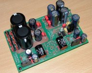
I'M BACK!!
Yesterday I received the long awaited board from Zang.🙂
It was a nice feeling to finaly hold it in my hands, although I've seen the thing for God knows how many hours on my screen during the development.
Couldn't wait to start stuffing the board to sadely realize I didn't had all the parts to finish it. In the attached picture you can see how far I've progressed.
The comments so far:
Nice quality of manufacturing
Very good layout (ahumm)
There are a few components that could used a bit more space, but nothing critical.
I will give an update as soon I have the remaining parts.
Regards
Attachments
Member
Joined 2002
GeWa said:I'M BACK!!
Yesterday I received the long awaited board from Zang.🙂
It was a nice feeling to finaly hold it in my hands, although I've seen the thing for God knows how many hours on my screen during the development.
Couldn't wait to start stuffing the board to sadely realize I didn't had all the parts to finish it. In the attached picture you can see how far I've progressed.
The comments so far:
Nice quality of manufacturing
Very good layout (ahumm)
There are a few components that could used a bit more space, but nothing critical.
I will give an update as soon I have the remaining parts.
Regards
Look's good for sure. Is that a tube i see 🙂 ( I mean socket for one )
- Status
- Not open for further replies.
- Home
- Amplifiers
- Chip Amps
- VBITNGC building & comment