The CFP-based bias generator appears as figure 22.33 on page 533 of Self's APAD6. Self inexplicably dismissed it in favour of the demonstrably inferior single transistor bias generator which he discusses ad nauseam.
Thank you. I will check it out.
Right now I'm trying to find the optimal bias setting for this amplifier. Unfortunately I'm finding that the optimal bias setting depends on the power level the evaluation is taken at. Still trying to sort this out.
This amplifier (at an initial bias setting of 40mV) produces the most THD (total, 2nd & 3rd on a spectrum analyzer) at about 5W into 8ohm dummy load.
Setting the optimal bias at 5W (using the spectrum analyzer to find the minima for THD total, 2nd & 3rd) is found to be 27mV. Setting the optimal bias at full power (45W into 8ohm for this amp, same spectrum analyzer usage) shows an optimal bias setting of 51mV.
Observing the crossover glitch on a scope from the distortion residue of a distortion analyzer is useless for fine tuning. The "glitch" changes shape and position (phase) as the bias is adjusted 1-2mV at a time, but its magnitude does not meaningfully increase until bias is grossly out of bounds.
I wonder if there is such a thing as "best" bias setting for all power levels, or does it shift with power level? I know we're dealing with crossover distortion and gm doubling as we slide thru what might be called the optimal bias point on a "wing" diagram of output stage gain.
Sorry, now I'm really off topic here. Seems like the can of worms never ends with audio amplifiers.
Usually, bias got setting at no any signal in amplifier input. The theory of complementary EF pair operation has been described by Mr. Oliver in far 1971
True, with a commercial amplifier where the service manual specifies a bias level, the bias is adjusted with no signal applied after a specified warm-up period.
In this case I am finishing a new amplifier design and have to determine what that value is myself. What I have read in books is, while helpful, not 100% definitive.
In this case I am finishing a new amplifier design and have to determine what that value is myself. What I have read in books is, while helpful, not 100% definitive.
The CFP-based bias generator appears as figure 22.33 on page 533 of Self's APAD6. Self inexplicably dismissed it in favour of the demonstrably inferior single transistor bias generator which he discusses ad nauseam.
I think to say he inexplicably dismissed it isn't fair. He states that CFP designs are prone to instability and he favors a simpler design. The schematic in his book doesn't include stabilization caps that might be needed to address this concern.
CFP bias generators are discussed in this thread: Vbe bias generator insights. User "Bonsai" has designs on his site that implement this (His NX amp for example). You can use these for reference to a real-world working example. You can also see the caps he has added along with their values.
There no any difference between commercial and diy amplifiers.
Silicone is same in both.
You can read Mr. Self's and Mr. Cordell's books, first of all.
And the paper by Mr. Oliver in Hewlett-Packard Journal No 2/1971.
It could gives you the answer.
Optimum value of idle current has to corresponds with resistance in emitters of output EF pair, at one hand. And couldn't be extremely small to prevent Ft and h21 of output transistors drops.
I think to say he inexplicably dismissed it isn't fair. He states that CFP designs are prone to instability and he favors a simpler design. The schematic in his book doesn't include stabilization caps that might be needed to address this concern.
CFP bias generators are discussed in this thread: Vbe bias generator insights. User "Bonsai" has designs on his site that implement this (His NX amp for example). You can use these for reference to a real-world working example. You can also see the caps he has added along with their values.
I also have a tendency to avoid CFP designs due to what I have read about their potential tendency toward instability. That is not to say I may not look into them on future projects, but I tend to be somewhat conservative regarding designs that might be prone to self destruction.
I have repaired three older NAD amplifiers with a dubious output stage design that were prone on one of the channels (L or R, don't remember) to cascade self-destruction complete with blowing the tops off the TO-264 output devices! Stability can be unforgiving and unexpected, especially with wildly varying speaker loads out there. It was odd that on all three amps it was the same channel......
I think to say he inexplicably dismissed it isn't fair. He states that CFP designs are prone to instability and he favors a simpler design. The schematic in his book doesn't include stabilization caps that might be needed to address this concern.
I don't think it is a valid excuse to say the CFP bias generator is prone to instability while advocating the use of the CFP as the output stage of his amplifiers. If Self found the CFP bias generator to be unstable, and I doubt this, then he should have presented solutions to this problem rather than resigning himself to the clearly inferior single BJT bias generator.
I don't think it is a valid excuse to say the CFP bias generator is prone to instability while advocating the use of the CFP as the output stage of his amplifiers. If Self found the CFP bias generator to be unstable, and I doubt this, then he should have presented solutions to this problem rather than resigning himself to the clearly inferior single BJT bias generator.
Perhaps he felt that the single BJT bias generator is good enough. I don't know his thinking.
I do know Cordell outlines many multi-transistor bias generators in his book (I only have Cordell Version 1), but almost all designs I have seen published or in commercial production (post 1990's) use the single BJT approach. Sometimes, especially for something as vital as bias stability, simpler can be better. Just ruminating - for the three stage output I am considering using on my next amplifier I have been looking into using more than one BJT in the bias generator in order to better match the temperature shifts of the pre-driver, driver and output devices.
With the "same load / speakers?"
I'm going to do the simu of #15 myself - I'm curious!
I'm sorry MarsBravo, I don't follow you. What same load/speakers?
What part of the schematic in #15 are you curious about? I've built a few of that amplifier (with small component value changes as I optimize it), perhaps I can shed some light.
... what I was refering to about the loads...It was odd that on all three amps it was the same channel......
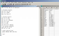
Did this fast analysis: problem is major in connecting input diff cs to Q11-Q19 cs. That's no good, very ps susceptibleWhat part of the schematic in #15 are you curious about?
Attachments
... what I was refering to about the loads...
Aah.. about the NAD amplifiers I mentioned. I have no knowledge about speaker loads, they were all burnt out when they showed up in my shop. Just curious it was the same channel in all three. And also seemed odd that the design omitted emitter resistors for the BJT output devices.
I now use 0.1ohm emitter resistors in my designs, but this was the first I had seen 0ohms. Odd
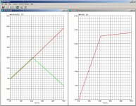
Single BJT bias generator with compensation resistor in its collector (as described in Mr. Self's book) is the best case of Ube splitter schemes. It's voltage drop is undependent from signal part of VAS output current and has close to symmetric transfer characteristic around VAS idle current. You can read about it on link in #25
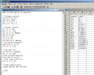
Including the dc-performance of the input differential current source.
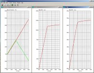
Keep in mind that this idcs dependency is amplified - in phase - to the bias circuit, rendering this topology to the quality of the ps instead of intrinsic stable. Hence the difference of 13 vs 39 ohms for R39. Feedback should only address one issue: signal control. No other fuss.
This is not my preference to amplification of audio signals, but granted.
Attachments
Did this fast analysis: problem is major in connecting input diff cs to Q11-Q19 cs. That's no good, very ps susceptible
Are you saying Q11 should be connected to Q9 instead of Q19? I have seen it done both ways. What is your thinking?
There are many related topics on this platform regarding zero E-Res designs by NAD, and with desparate pleas for guidance to solve defunct amps. It renders ultimately to the bin: it's all about selling-buying-disposing. Anyone for a free lunch?And also seemed odd that the design omitted emitter resistors for the BJT output devices.
- Home
- Amplifiers
- Solid State
- VBE Multiplier current compensation resistor