Hi!
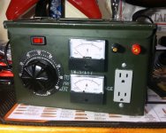
I recently acquired an old Standard "Adjust-A-Volt" variac which I've rigged up in a case with volt and ammeters output plugs and posts, to make it useful for amp work.
My problem is that I can't seem to figure how to wire it correctly to get the voltages out that I'd expected.
This one is a little different than some I've seen in that instead of a single panel of numbered terminals, it has 5 terminal posts arranged around one half of the perimeter of the transformer body. But they're numbered 1-5 so I thought my job would be easy.
Based on reading a lot of threads on variacs, I figured that if I wired it like this:
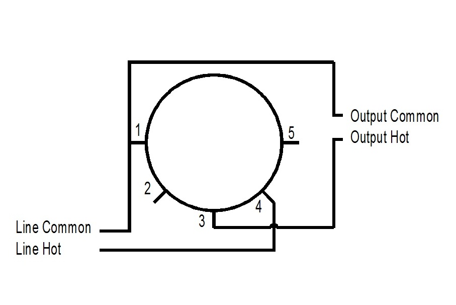
I'd get out a linear voltage rise from zero to about 140V.
Well, that t'aint what happened. 🙂
What I get out is 20V at the 0% setting, which drops to 0V as I bring it up to about the 15% mark. Then it starts to rise again and tops out at the 100% setting giving me my full house voltage of about 122 V.
Ok, so that's not the end of the world. I at least can get a smooth 0-122V range, but it bugs me that it's not done correctly and I get this bit of opposite phase voltage at the bottom of the range.
So, based on my incomplete understanding of how these things are wired, I figured I could just eliminate the "boosting" effect and wire it like this:
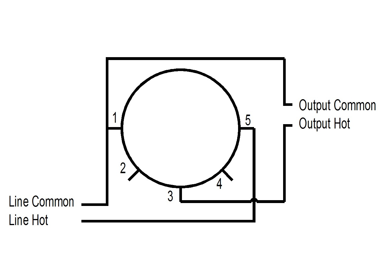
That was not a good idea. 🙁 I got weird readings, very briefly, from the volt meter and then my 2A fuse blew.
So now I'm pretty convinced that my variac's numbering of the terminals is not really the same as all the others I've read about.
But I can't quite figure out how they must be based on the results I'm getting.
The one thing I think I'm sure of, is that there is a big copper bar running from Terminal 3 to the center shaft, which makes me somewhat confident that 3 is indeed the wiper, as every other Variac I've read about.
Can anyone help me get over my mental block and see what's going on? How should I wire this thing?
Thanks!
I recently acquired an old Standard "Adjust-A-Volt" variac which I've rigged up in a case with volt and ammeters output plugs and posts, to make it useful for amp work.
My problem is that I can't seem to figure how to wire it correctly to get the voltages out that I'd expected.
This one is a little different than some I've seen in that instead of a single panel of numbered terminals, it has 5 terminal posts arranged around one half of the perimeter of the transformer body. But they're numbered 1-5 so I thought my job would be easy.
Based on reading a lot of threads on variacs, I figured that if I wired it like this:
I'd get out a linear voltage rise from zero to about 140V.
Well, that t'aint what happened. 🙂
What I get out is 20V at the 0% setting, which drops to 0V as I bring it up to about the 15% mark. Then it starts to rise again and tops out at the 100% setting giving me my full house voltage of about 122 V.
Ok, so that's not the end of the world. I at least can get a smooth 0-122V range, but it bugs me that it's not done correctly and I get this bit of opposite phase voltage at the bottom of the range.
So, based on my incomplete understanding of how these things are wired, I figured I could just eliminate the "boosting" effect and wire it like this:
That was not a good idea. 🙁 I got weird readings, very briefly, from the volt meter and then my 2A fuse blew.
So now I'm pretty convinced that my variac's numbering of the terminals is not really the same as all the others I've read about.
But I can't quite figure out how they must be based on the results I'm getting.
The one thing I think I'm sure of, is that there is a big copper bar running from Terminal 3 to the center shaft, which makes me somewhat confident that 3 is indeed the wiper, as every other Variac I've read about.
Can anyone help me get over my mental block and see what's going on? How should I wire this thing?
Thanks!
Attachments
First and more important rule ... use a ligthbulb as a current limiter in series with the mains to limit current while testing otherwise you may damage the variac ..
Then find the number of the wiper ( locate the wiper terminal )
I posible take a picture and we will try to help ..
Then find the number of the wiper ( locate the wiper terminal )
I posible take a picture and we will try to help ..
How should I wire this thing?
Here's a diagram. The neutral terminal and the wiper contact at full CCW rotation.
Remember there is a boost winding, so input AC does not connect to the full CW end
of the winding, but rather a tap. Be sure to properly fuse these units. Remember, there is NO isolation.
https://www.youtube.com/watch?v=6sqoZk4W9tU
https://www.google.com/search?q=var...=EKNQV_rvA8bWmwG7lrOABw#imgrc=_IVvIAmFu3IgUM:
Last edited:
If the variac is a '' open type '' ( no housing )
Turn the knob full counterclockwise ( in this position output voltage should be zero ) locate the wiper .. find the terminal number closer to the point where the wiper is ( the wiper is in contact with the winding .. close this spot on the winding there must be a wire connecting to the winding .. this wire run to a terminal .. ) this terminal should be connected to mains neutral and also to load neutral terminal .
Turn the knob clockwise to the point where you expect to have output voltage at 100% ..... locate the wiper .. find the therminal numer ..( the wiper is in contact with the winding ..there must be a wire connecting to the winding close this spot .. ) this terminal should be the '' live '' from mains
load of course connected to wiper ...
Thanks guys!
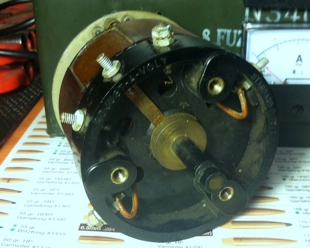
Here are a couple of pictures:

The terminals:
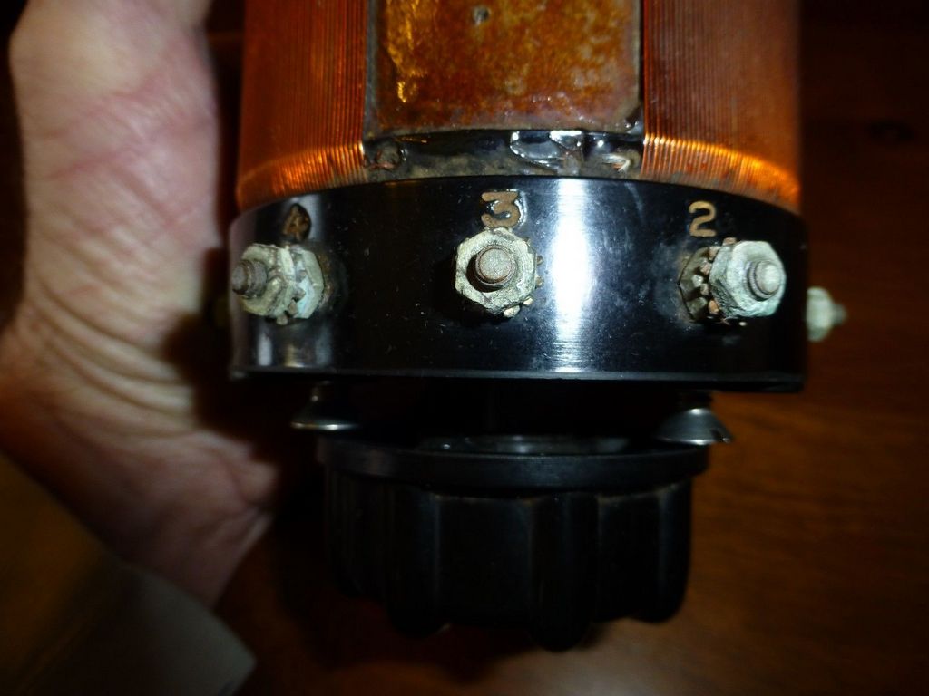
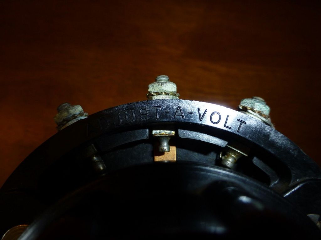
And the terminals from the rear, centered on "3" which I believe is the wiper. (You can see the copper strip that runs to the center spindle.)
Here are a couple of pictures:
The terminals:
And the terminals from the rear, centered on "3" which I believe is the wiper. (You can see the copper strip that runs to the center spindle.)
Attachments


If you have a reasonably precise meter I would think you could determine a lot by measuring the resistance between terminals:
1-2
2-3
3-4
4-5
and so on...
Found this link
Antique Radio Forums • View topic - FS: Three Powerstat 116U 7.5A 1KVA Variacs.
1-2
2-3
3-4
4-5
and so on...
Found this link
Antique Radio Forums • View topic - FS: Three Powerstat 116U 7.5A 1KVA Variacs.
OK guys, I'll get on this as soon as I have a chance to get it out of my case and run the tests. Thanks much!
OK!
Here are some more pictures.
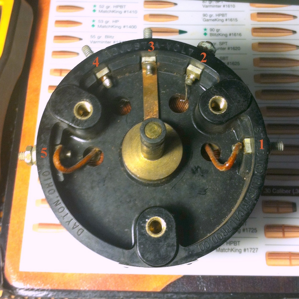
A better view of the front of the device, showing the terminals and their leads down into the winding:
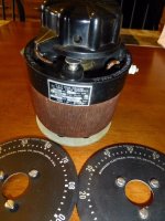
A general shot:
With the wiper turned all the way to 0%, it actually seems to line up with Terminal 2, giving me a glimpse at why I'm probably seeing these weird readings:
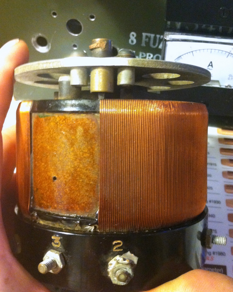
And here's where the wiper would stop if I turn it to 100%. Going PAST 5, around to 4. Maybe it's just that the numbers don't correspond at all to the numerical percentages of output and I was too silly to grasp that before... 😱
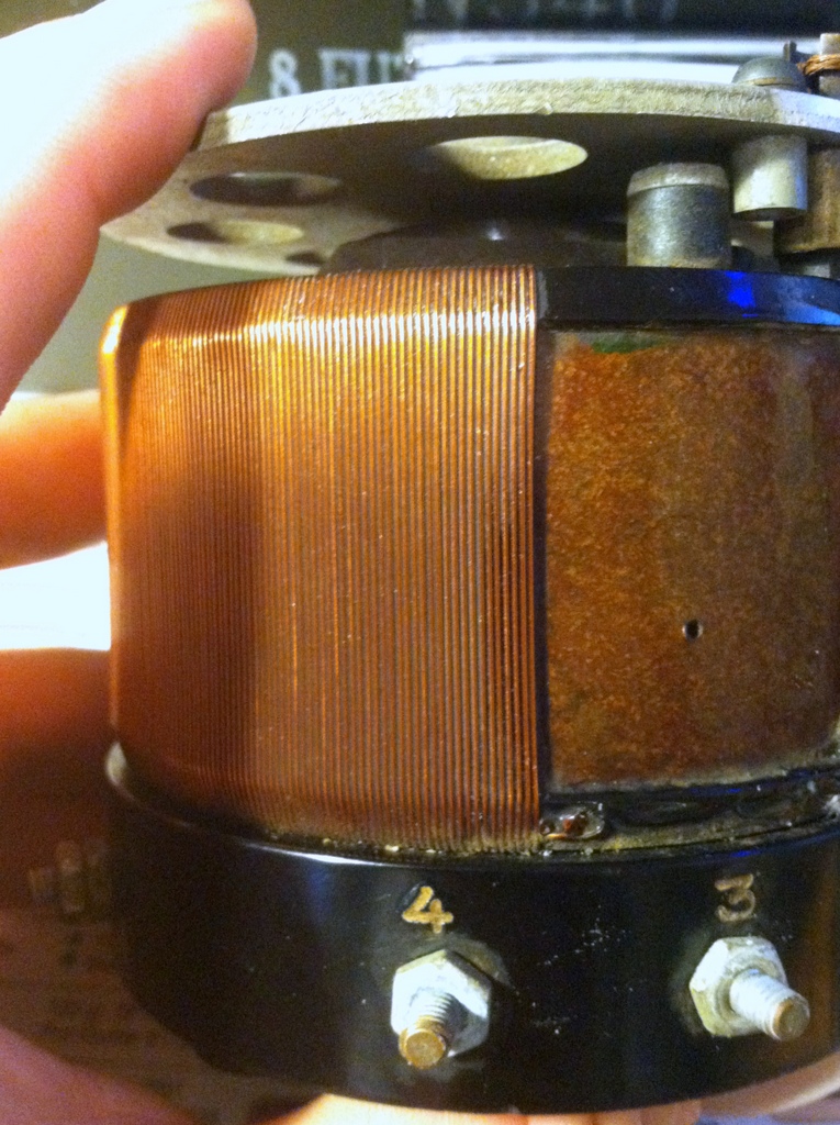
As soon as I get it wired up the way you suggested, I'll get back with the voltages.
Here are some more pictures.
A better view of the front of the device, showing the terminals and their leads down into the winding:
A general shot:
With the wiper turned all the way to 0%, it actually seems to line up with Terminal 2, giving me a glimpse at why I'm probably seeing these weird readings:
And here's where the wiper would stop if I turn it to 100%. Going PAST 5, around to 4. Maybe it's just that the numbers don't correspond at all to the numerical percentages of output and I was too silly to grasp that before... 😱
As soon as I get it wired up the way you suggested, I'll get back with the voltages.
Attachments


With my current limiter (300W bulb) in series in the mains hot line, connected to Terminal 4, and the house mains common at Terminal 2 I get...
1 -- 2: 18.1 V
1 -- 4: 98.3 V
1 -- 5: 79.0 V
2 -- 4: 117.5 V
2 -- 5: 97.4 V
4 -- 5: 19.0 V
And I get a nice linear sweep from 0V to 122 V as I move the dial from 0% to 100%! Great!
I imagine there's another way yet to wire this to get that boost up to 140V, but as I've not yet figured out why I'd want that, perhaps I don't care. 🙂
Thanks guys!
Ok
You have maximum voltage betwen #2 & #4 ...these must be the 2 end of the winding
A low voltage betwen 1 & 2 so #1 must be a tap close to #2
Alow voltage betwen 4 & 5 so #5 must be a tap close to #4
#3 is the wiper
So neutral of the source and neutral of the load should be at #4 ( 2 wire on this one )
Hot side of the LOAD at #3 with a fuse selected according to the variac nominal current
Then the mains ( HOT side ) connect to #2 with a second fuse selected according to the variac nominal current ... and output voltage will be ajustable from 0% to 100% ( no overvoltage possible )
To make overvoltage possible move the main from #2 to #1 ( dont forget the fuse )
Attachments
- Status
- Not open for further replies.
- Home
- Design & Build
- Equipment & Tools
- Variac Wiring Question