Hey George,
I'm curious to hear your take on this idea...an old but interesting circuit idea!
Variable UL Anyone? - Triode_Kingdom - Tube DIY Asylum
Happy New Year! from Adam in Ashland, Oregon
I'm curious to hear your take on this idea...an old but interesting circuit idea!
Variable UL Anyone? - Triode_Kingdom - Tube DIY Asylum
Happy New Year! from Adam in Ashland, Oregon
The current through G2 is far from constant between different drive levels. Voltage drop between pot and wiper will change.
Feed G2 with a source follower and it should work. Mind the voltage rating of the FET though.
Happy new year!
Feed G2 with a source follower and it should work. Mind the voltage rating of the FET though.
Happy new year!
The downside of this circuit occurs when the plate voltage swings above B+.
The screen supply via the triode can not swing above B+ so it does not track the plate voltage as it does when driven from a transformer Distributed Load tap.
The screen supply via the triode can not swing above B+ so it does not track the plate voltage as it does when driven from a transformer Distributed Load tap.
They have the follower marked as "B ++", so maybe the designer intended it to start from a higher potential to give it more swing?
Regardless, just the extra power supply, besides the extra tube per channel, seems to make this more of a curiosity / plaything, rather than a real UL substitute in today's world.
Win W5JAG
Regardless, just the extra power supply, besides the extra tube per channel, seems to make this more of a curiosity / plaything, rather than a real UL substitute in today's world.
Win W5JAG
I didn't read the notes, yes it is expected that B++ Be 150V higher than B+.
That will help, but may not solve the issue as the plate voltage can swing almost 2X B+.
I would simply opt for the UL OPT to begin with.
Unless:
One wants to vary the UL ratio to determine how the output tube in question behaves. Some tubes are optimum at other than 40% tap ratio.
Switching from UL, to Pentode to Triode operation will also require adjusting the cathode resistors for the output tubes and alluded to by the star note.
I read the text, but I confess I didn't read the notes, either ...
I guess the bottleneck would be how much voltage you can actually put across the triode?
Inexpensive is a misnomer in today's world, I think, but it might be fun to play with. It would not be too hard to rig up the little test mule I made in the mosfet less TSE thread to try this, once I get my other Trainwreck project built and behind me.
edit: in addition to the bias, I would expect the gain to change as it goes from pentode to triode, so the NFB loop will not be right, and the drive may not be right.
Seems problematic, but might be fun to tinker with.
Win W5JAG
Last edited:
I'm curious to hear your take on this idea
I'm guessing that this is one of those circuits that got published in a magazine with little or no testing, or several important details have been left out. If this was operated in triode mode and cranked up loud the cathodes of the 12AU7's would attempt to follow the plates. They would run out of voltage headroom even with the boosted B++ voltage. So lets assume that there is enough headroom, or the amp wasn't played loud enough to run out of voltage. The cathodes of the 12AU7's are moving in opposite directions and one should reach about twice the B+ voltage while the other is near zero. The HK breakdown spec would be seriously violated making the 12AU7 very unhappy.
Feed G2 with a source follower and it should work
Tried that......makes for some dead mosfets, as the gate voltage goes way above the drain unless the drain is bootstrapped or tied to a higher voltage supply.
This concept was explored in detail by myself and some other knowledgeable people about 12 years ago. My answer to the dead mosfet situation is in post #22 here:
Adjustable distributed load discussion
I improved that circuit with two mosfets, one to adjust the DC voltage on G2, and a second to scale and buffer the AC voltage on G2, primarily to experiment with "UL" on sweep tubes that have a low G2 voltage rating.
Eight years went by and it seems that nobody ever came up with a good resolution to making this all work right. In post #182 of the same thread I discussed my idea for a "Grand Unified Theory" (GUT) board that essentially had one or two mosfets tied to every electrode on a tube.
I have worked on that idea off and on for several years and it's finally beginning to show some promise. Here are the curves plotted manually for a $1 TV sweep tube. I was taking measurements with cheap meters while turning knobs on analog power supplies, hence the slight error in the position of the purple curve 4th from the left. Why mess with UL when you can "make" triodes like this out of $1 sweep tubes!
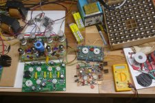
The board behind the SPP board is s push pull test amp. It makes 75 WPC from a regulated 500 volt supply, and 50 WPC with an Antek toroid for power. The green perf board and DIY PC board to the right of the SPP is the prototype of that amp. A proto SE version with a bigger sweep tube is being developed now.
Attachments

- Status
- Not open for further replies.
- Home
- More Vendors...
- Tubelab
- Variable Triode-Ultralinear-Pentode modes?