Ugh. In some perfect theoretical electric filter world, where the termination load is a resistor, that might work. In real life with a resonance impedance peak, it is much more complex. There's a thread somewhere (this forum? AVS?) about actually making that work although I thought that was with a capacitor and inductor. OR you can start trying to make a Zobel network in parallel to knock down the impedance peak, also complex and expensive. And then when the impedance changes some due to ambient conditions or the woofer heating up at loud volumes, not quite correct. To me, a well designed EQ is better than these other foolings around (except maybe adding a port)there’s a trick to add a capacitor in series with the woofer. It will produce a boost at the low-end but also change the slope from 12 to 18dB/oct. Has anybody ever heard about this? What do you think about it, please?

In some perfect theoretical electric filter world, where the termination load is a resistor, that might work. In real life with a resonance impedance peak, it is much more complex.
As far as I know, the idea is to synthesize a third-order filter using the mechanical resonance and the extra capacitor. That is, it works thanks to the impedance peak.
head_unit, good point since you take what you get, like with a ported box.
Marcel is correct, in combination with the impedance peak you get some interesting effects. You can do first or second order, naturally the second order gives you another resonance to work with so you have to design it purposefully.
It was a good option for commercial speakers because it is a self contained modification.
"3rd order" capacitor boosted alignments probably work best with high-ish qtc sealed boxes.- but you could try the magic 450uF for 8 ohm cap to see and hear what happens - it can push the woofer quick to xmax - the "boost" occurs from the combination of lowered Z at the peak area pulling more current and driven by an ~ constant voltage source - so would do about nothing with some zero feedback tube amps
If you know / measure your woofer's parameters and box volume then you can use hornresp - Filter Wizard - "passive" to calculate the "3rd order" sealed box'.

If you know / measure your woofer's parameters and box volume then you can use hornresp - Filter Wizard - "passive" to calculate the "3rd order" sealed box'.
Wow! It sounds interesting with the trick of modifying the 2nd order to 3rd order slope by using a capacitor. But, how about the calculation of the capacitor’s value to be used? Anyway, I found an approximating calculation online but it stated it’s an approximation. Yet, I discovered there’s a paper published by Thiele named “Closed-box loudspeaker with a series capacitor” and I’m really interested it. However, I couldn’t access it via online. So, if there’s anyone who would like to give me a hand, please PM me. TIA
Install VituixCAD, open enclosure tool from Tools menu, choose your driver and box alignment, box size, and use Cs on the filter window to experiment. Even better if you have measured data, just import into VituixCAD, or any other xover tool, add series cap and see what happens.

Last edited:
Here is how to intuitively think about this, about link between mechanical domain and electrical domain, and how they interact:
impedance peak is due to mechanical resonance of the mass and spring. The cone moves easily at the resonant frequency, low force applied makes large movement as with any mass and spring system. As the cone moves, backEMF voltage is generated in the motor which would induce current into the circuit that would make force opposing the movement (velocity), the driver dampens itself at the resonance, there is electrical damping. You could make force to move the cone with your finger, or apply current through voice coil so the driver motor makes the force.
If you take out datasheet of the driver you are having there, see how the frequency response measurement and impedance measurement are made using constant voltage. And this is important, applying constant voltage means circuit impedance outside the driver must be very low in order to maintain constant voltage, so the driver dominates the circuit impedance, which means the driver takes part how much current the voltage (amplifier) makes in the circuit. Impedance is literally relationship of voltage and current and it is the current that makes voice coil move, not voltage. Acoustic output depends on current in the circuit the voice coil is part of, thus the driver EQ's itself as it dominates how much current the voltage makes being the dominating impedance. Datasheet frequency response shows situation where the driver EQ:s it's own acoustic output facilitated by low circuit impedance in series with the driver. Impedance graph is basically the EQ curve the driver makes with constant voltage sweep.
Now, if you selectively increase circuit impedance in series with the driver at some particular frequency, you'd remove the EQ ability of the driver! You'd reduce backEMF voltage current, you'd reduce the opposing force. While of course possibly added another EQ with the impedance, it's a combined effect. When you add a big cap in series, you'd cause a high pass filter for amplifier current, but also high impedance for the backEMF current, which reduces the driver electrical damping: at the resonance the cone moves very easily with even very small force and since circuit impedance for backEMF is now higher (a lot higher), it makes much less opposing current which basically means reduced electrical damping. What you've done by adding the capacitor is you've mostly reduced the drive ability to dampen itself electrically at the resonance, and you'd measure more acoustic output.
Now if you removed (electrical) damping, the driver would "resonate more" and show peak in acoustic output, as the constant voltage input would make the cone move more than with electrical damping "braking" it, more than seen in frequency response measured with constant voltage where the electrical damping is maximal. There is other ways to add damping, like adding losses in the spring, which is combination of suspension of the driver and the air inside a box, if you have one. Aperiodic port would be a loss in the spring and function as mechanical damping, increase total damping of the resonance which would reduce acoustic output at the resonance. To counteract increased mechanical damping (aperiodic port) you could decrease electrical damping so the total damping ends up what ever you wish. In the end all you have to do is look at the frequency response, and could just use EQ. Anyway, it's fun thought experiement to think about this stuff, how everything works, as it gives understanding to utilize means to your advantage.
There is likely more details into all this, but I think this is relatively easy practical level for DIY enthusiast to think about the stuff, and then use simulator to check out how it works out.
Last edited:
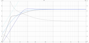
I've tried simulation in VituixCAD as @tmuikku suggested. Here is the result.
The light blue line is Q = 0.5. (Original design)
The dark blue line is Q =1.0. (Assume to be target)
The black line is Q = 0.5 with a 1,500uF capacitor in series.
It's likely that it might not follow the theory because the response was boosted at below 40Hz. Above 40Hz was slightly reduced. I'm not sure if my interpretation is correct. Please advice me.
Attachments
Just vary the Cs value and you see how it works, and if it's useful to you. The smaller the capacitor, the higher the impedance at some particular frequency.
What the series cap allows to do is use somewhat smaller enclosure. If you want to match some target response, adjust both the cap and enclosure size. If you want to keep enclosure size constant, then you must change driver and the cap to meet a target.
Some random example:
a driver in 47litre closed box has system Q of 1

Adding a cap "extends" the lows a bit

Or, I could almost halve the enclosure size with added capacitor to reach similar response as Q1

Whether series capacitor is useful depends on what you want to achieve. If you can use any sized box I don't see why you'd need a series cap, for example. You could build a magic box though, a capacitor allows you to vary your system response, an EQ 😀 Don't tell anyone it is an EQ.
What the series cap allows to do is use somewhat smaller enclosure. If you want to match some target response, adjust both the cap and enclosure size. If you want to keep enclosure size constant, then you must change driver and the cap to meet a target.
Some random example:
a driver in 47litre closed box has system Q of 1
Adding a cap "extends" the lows a bit
Or, I could almost halve the enclosure size with added capacitor to reach similar response as Q1
Whether series capacitor is useful depends on what you want to achieve. If you can use any sized box I don't see why you'd need a series cap, for example. You could build a magic box though, a capacitor allows you to vary your system response, an EQ 😀 Don't tell anyone it is an EQ.
Last edited:
Sometimes the series cap trick works, sometimes does not and the results are not optimal for any value you try because there is interaction with the box volume and the speaker impedance.It's likely that it might not follow the theory because the response was boosted at below 40Hz. Above 40Hz was slightly reduced. I'm not sure if my interpretation is correct. Please advice me.
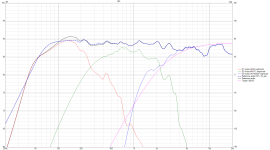
This is my first ever speaker in the '80s, an Audax HD24 driver in closed box, a typical system (like yours). You can try any value you want and this is the best you can get with the cap (solid line).
The trick has also been used by Kef in the past. In this case the FR it's better with the cap (solid line).
Attachments
AFAIK the capacitor ‘trick’ is and has been used extensively, Neville Thiele holding the credits (more or less), since the early eighties. It actually still is a no-brainer for passive, small closed enclosures. The app Basta! to me still is unsurpassed for these things, mainly because of easy use and reliable results.
The old Keele B6 arrangement also came by. To me still a very viable and simple option for reflex systems, both protective and extending low range.
The old Keele B6 arrangement also came by. To me still a very viable and simple option for reflex systems, both protective and extending low range.
I wasn’t totally satisfied with their bass response. I think it’s too TIGHT and a bit too LOW efficiency. As a result, it led me to add an active equalizer to the system at present.
i guess it was not a linkwitz transform - with that you could try out any Q (and resonance) you want - assuming you accurately know the existing values
- Home
- Loudspeakers
- Multi-Way
- Variable Qtc on closed enclosures