Hello,
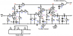
I build this phono preamp from valve wizard:
The Valve Wizard
When I finished the build I connected to my amp and I notice that the left channel sounds louder than right channel. Okey, time to connect an oscilloscope and insert 1khz signal, and yes, the left channel sounds louder than right channel. I try to adjust the internal trimm, but its not enough, I check all the components over and over, I change the tubes, for new ones. The only way I can adjust more or less precisely is if I elevate the heaters to 7v and down the HT to 200 or 220 vdc.
I have paralell heaters
RIAA split
V1 and V2 ECC83
V3 ECC82 I tryied a ECC88 to
And ideas?
V1 and V2 aren’t matched, but I supose that the prupose of the trimm is for it...
Thanks.
the left channel sounds louder than right channel.
Likely it's just that the tubes vary in gain. There's no nfb to normalize their gains. Try measuring the 1kHz gain of each tube stage, disregarding the RIAA network to see where the gain difference is, first or second stage. If you have plenty of gain,
try removing the cathode bypass capacitors and see if this makes the gain similar enough between channels.
Do the tubes look the same. Perhaps it is mis-label. Regardless, you can add a small resistor between V2 cathode and the trim balance pot on the loud channel. That should do it.
Morning,
new readings. I follow the input signal, from the first component.
C2 ( left channel ) have more signal than C22 ( right channel ).
Voltage readings from V1:
1: -1.045
2: 1.615
3:
4: 210
5: -4.05
6: 1.942
7: 1.585
8:
9: 228.1
V2
1: -1.078
2: 0.400
3:
4: 138.8
5: -4.06
6: 1.956
7:
8:
9: 141.1
V3
1: -1.010
2: 29.56
3: 30.07
4: 248.8
5: -4.06
6: 1.980
7: 26.20
8: 26.78
9: 250.6
Morning,
new readings. I follow the input signal, from the first component.
C2 ( left channel ) have more signal than C22 ( right channel ).
Voltage readings from V1:
...
Are you sure you are reading the pins correctly?
Those voltages do not make any sense?
Alan
I see that!
So I will use your method of numbers. (Clockwise from the top of the socket 🙂.
Pin 2 should be very similar to pin 7 on each valve. That's the cathode (3 and 8 from below).
Pin 4 should be very similar to pin 9 on each valve. That's the anode (1 and 6).
So what looks wrong?
1: -1.045
2: 1.615
3:
4: 210
5: -4.05
6: 1.942
7: 1.585
8:
9: 228.1
V2
1: -1.078
2: 0.400 should be much higher 2 to 5 volts ?
3:
4: 138.8
5: -4.06
6: 1.956
7:????
8:
9: 141.1
V3
1: -1.010
2: 29.56
3: 30.07 this should be the same as you have on pin 4 of V2 so ~ 140v.
4: 248.8
5: -4.06
6: 1.980
7: 26.20
8: 26.78 this should be the same as you have on pin 9 of V2 so ~ 140v.
9: 250.6
So check what you have on V2 pins 2 and 7 again.
Then look why you do not have 140 volts on the grids of (pins 3 and 8) of V3.
Once you have fixed that, the voltage on pins 2 and 7 will go up to about the same too.
Alan
Okey,
I have made new measeures:
Now, it correct valve pins.
V1
1: 242.1
2: X
3: 1.548
4: 2.046
5: -3.90
6: 239.9
7: x
8: 1.552
9: -0.922
V2
1: 154.6
2: x
3: x
4: 2.063
5: -3.89
6: 138.8
7: x
8: x
9: -0.913
V3
1: 251.9
2: 24.40
3: 26.96
4: 2.103
5: -3.80
6: 251.7
7: 26.70
8: 26.25
9: -0.840
I haven't any reading on V2 pins 2, 3, 7, 8...
Okey,
I haven't any reading on V2 pins 3, 8...
Is D2 diode reversed? If not sure, try lift one pin up and see what happen.
I think he is counting pins the wrong way.
Yes, on top of the pcb, count counterclockwise from the space.
New readings… I hope that it helps.
V1 plate voltage is too high. Try a 1k resistor instead of D1.
Then V1 voltages should be about the same as V2.
V3 grid and cathode voltages are also way off. Check/replace D2.
Check C11, make sure it is not shorted. Try a different V3.
Last edited:
... I have parallel heaters ...
I have had a look at the build guide now.
So you have installed the links in T1-T2 and in T3-T4 for parallel heaters?
What heater voltage are you inputting to the board?
6 volts or 12 volts?
From the correctly numbered table in post #10, you only have 6 volts between any of the pins 4 and 5.
V1
4: 2.046
5: -3.90
V2
4: 2.063
5: -3.89
V3
4: 2.103
5: -3.80
As you are using ECC82 and ECC83 you should have 12 volts and be using a 12 volt supply...
(6 volts would be fine for ECC88 / 6N1P types.) Alan
Last edited:
+1. Check you heater voltagesI have had a look at the build guide now.
you only have 6 volts between any of the pins 4 and 5.
As you are using ECC82 and ECC83 you should have 12 volts and be using a 12 volt supply...
(6 volts would be fine for ECC88 / 6N1P types.) Alan
Yes I've installed the T1-T2 and T3-T4 links. My heater supply is 6.3v. I change V3 for a ECC88.
And this are the new readings of two channels.
left — imgbb.com
right — imgbb.com
And this are the new readings of two channels.
left — imgbb.com
right — imgbb.com
ECC82 and ECC83 need 12V for the heater!Yes I've installed the T1-T2 and T3-T4 links. My heater supply is 6.3v. I change V3 for a ECC88.
- Status
- Not open for further replies.
- Home
- Amplifiers
- Tubes / Valves
- Valve Wizard Tube Phono Preamp