If you only need a few milliamps 6H6 was used as a detector in various radio receivers. Its a double diode.
38HE7/xxHK7,
Diode can take PIV 4.5kv and massive frequency spikes with peak iA of 1.2A, steady 200m/a while the beam pentode inside can conduct half an amp.
Makes a nice P-P 25W amp if you know how.
Diode can take PIV 4.5kv and massive frequency spikes with peak iA of 1.2A, steady 200m/a while the beam pentode inside can conduct half an amp.
Makes a nice P-P 25W amp if you know how.
Should get 25W PP strapped as triodes if you ignore the ratings and run 320V @ 60mA into a 2 - 3k load.
If I can do that with 6P31S, I could do it with *HE7.
If I can do that with 6P31S, I could do it with *HE7.
Gas-filled devices are more effective, but also much slower.
Hard-vacuum devices are almost ideal regarding dynamic performances.
I began to set up a test circuit using a PY88 and the results are quite impressive.
At the moment, the oscillograms are still a bit unclean, but that's mostly caused by the breadboard test setup: the DUT is subjected to a 300V squarewave having switching times of 10~20ns, and the slightest parasitic coupling causes ringing.
When I'll get decent waveforms, I'll post them, but the preliminary results look staggering: no hint of forward or reverse recovery artefacts, even under the extra-harsh conditions of the test: forward current of 150mA, switched to -300V without slope or any form of current limiting. The most brutal test you can think of.
Even more interesting is the behaviour with a UF4007 substituted for the PY88: this time, the forward and reverse recovery artifacts are monstrous, with the peak Irr exceeding 1.5A
More on this tomorrow, but for the moment tube undeniably rules.....
I began to set up a test circuit using a PY88 and the results are quite impressive.
At the moment, the oscillograms are still a bit unclean, but that's mostly caused by the breadboard test setup: the DUT is subjected to a 300V squarewave having switching times of 10~20ns, and the slightest parasitic coupling causes ringing.
When I'll get decent waveforms, I'll post them, but the preliminary results look staggering: no hint of forward or reverse recovery artefacts, even under the extra-harsh conditions of the test: forward current of 150mA, switched to -300V without slope or any form of current limiting. The most brutal test you can think of.
Even more interesting is the behaviour with a UF4007 substituted for the PY88: this time, the forward and reverse recovery artifacts are monstrous, with the peak Irr exceeding 1.5A
Sounds pretty amazing. I am patiently awaiting the scope pics. It would be cool to see what would happen if you supstitute an indirecty-heated-regular full wave rectifier instead of a damping diode.
Even more interesting is the behaviour with a UF4007 substituted for the PY88: this time, the forward and reverse recovery artifacts are monstrous, with the peak Irr exceeding 1.5A
...
Not a big surprise ...
in a SS diode' s PN junction a region which is depleted of charges opposes a region crowded with charges, and what is imortant is that both these regions are part of a crystal lattice and not in a vacuum; that makes all the difference because to override this situation of disequilibrium in a lattice a certain amount of energy is required - like thermal energy or light - to recombine these separated charges ... you can either wait for that to happen naturally which takes a considerable amount of time; or you can try to enforce that by applying an external reverse electric field; the amount of energy needed to re-establish equilibrium in the lattice is what causes these enormous currents ...
not so in a vacuum diode; there are no regions filled with opposing charges; all there is are the electrons in an otherwise empty space; reverse the external electric field and those electrons either start moving or stop moving - almost instantly and almost effortless ....
....behaviour with a UF4007 substituted for the PY88: .....
@Elvee: it might be interesting to see how a Shottky diode behaves in the same setup ...
it should be a lot closer to a vacuum diode
@Elvee: it might be interesting to see how a Shottky diode behaves in the same setup ...
it should be a lot closer to a vacuum diode
I don't think you could use a shottky in this instance because it couldn't withstand the high voltages. Also, the UF4007's reverse recovery time is fast enough for rectification up to 100khz I believe.
I guess you didn't know there are HV Shottky SiC diodes...
This one is 3300V/40A: GC50MPS33H
Who cares that it's 265$ a piece! LMAO
Realistically though, there are many 1200V SiC diodes, lots of 600V ones, and 1700V is alto available. Most of which are under 10$
This one is 3300V/40A: GC50MPS33H
Who cares that it's 265$ a piece! LMAO
Realistically though, there are many 1200V SiC diodes, lots of 600V ones, and 1700V is alto available. Most of which are under 10$
Last edited:
EY81, EY88, PY81 and PY88 have been proven to work well at frequencies higher than ~ 30MHz in a linear amplifier for radio-amateurs (connection with a "clamp-tube").
I was thinking about the same. The European analogy, the EAA91/6AL5, was designed for FM demodulation at an IF of 10.7 MHz. Vacuum diodes in general are able to rectify without timing issues.If you only need a few milliamps 6H6 was used as a detector in various radio receivers. Its a double diode.
Best regards!
Here are the test results.
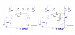
These are the test setups for the reverse and forward recovery behaviour.
They might look odd, and could probably be improved, but I didn't want to twist my mind too much for a one-off, and I wanted everything to be GND-referenced, to ease the connections and avoid potentially dangerous situations, both for the circuit and myself.
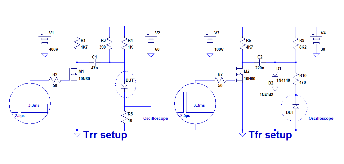
To minimize the dissipation, the circuit operates at a very low duty-cycle, and both version are using the same basic engine.
To get a good luminosity, the scope has to work in digital mode, which explains the lack of smoothness of the trace
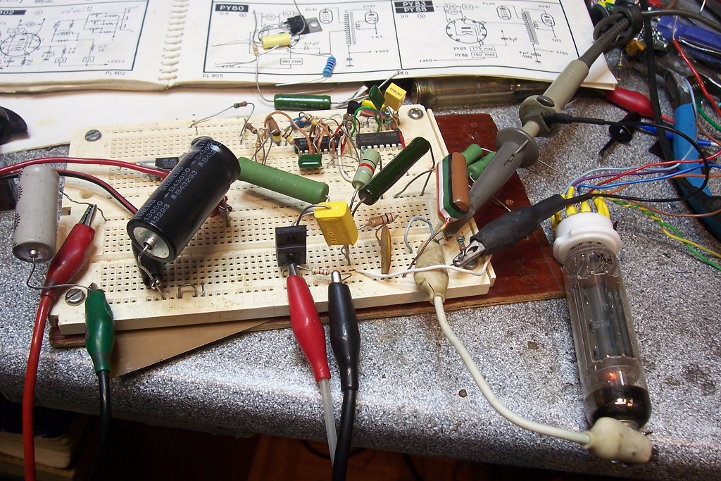
This is the physical implementation of the Trr setup:
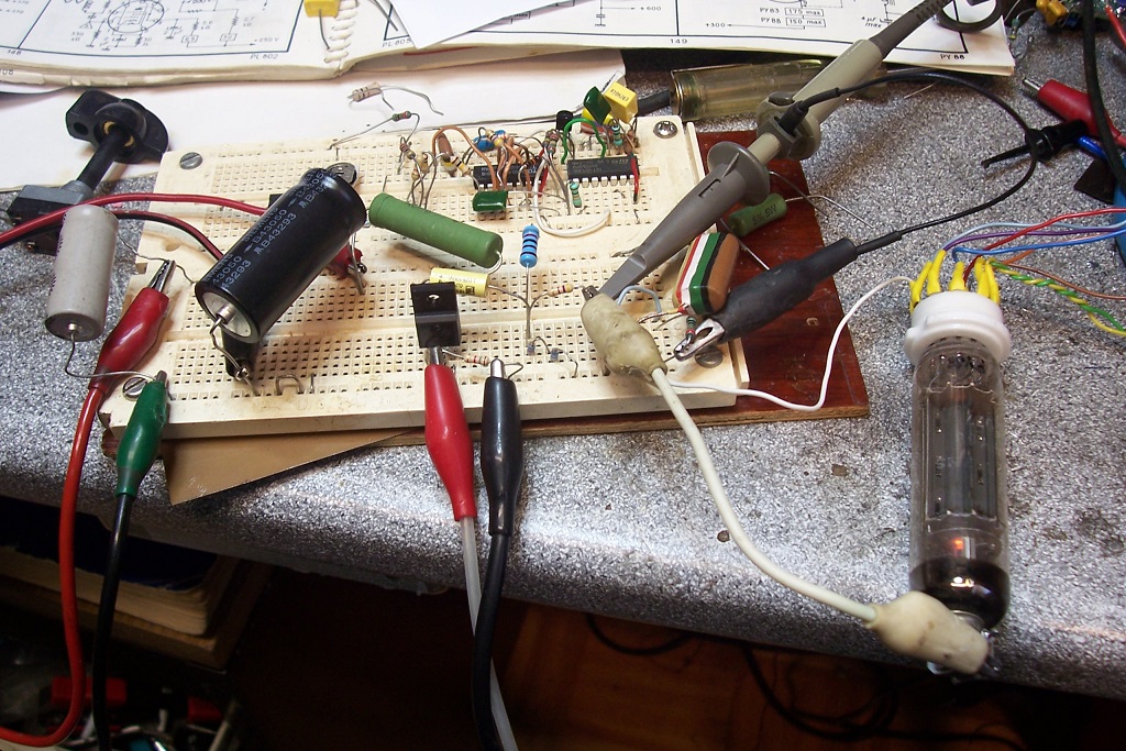
And this is the Tfr:
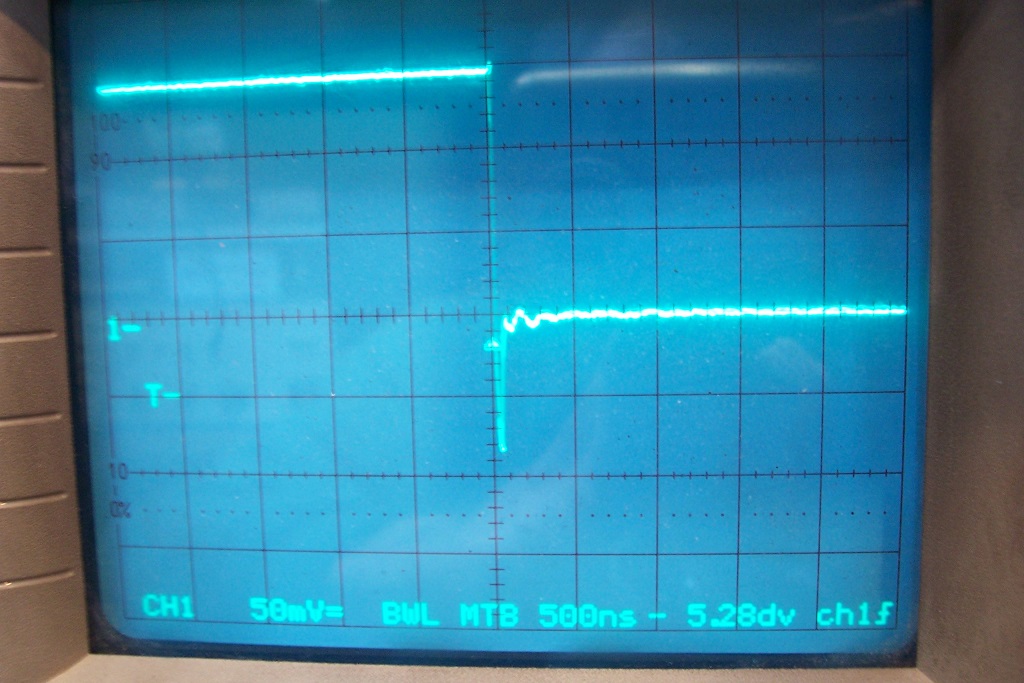
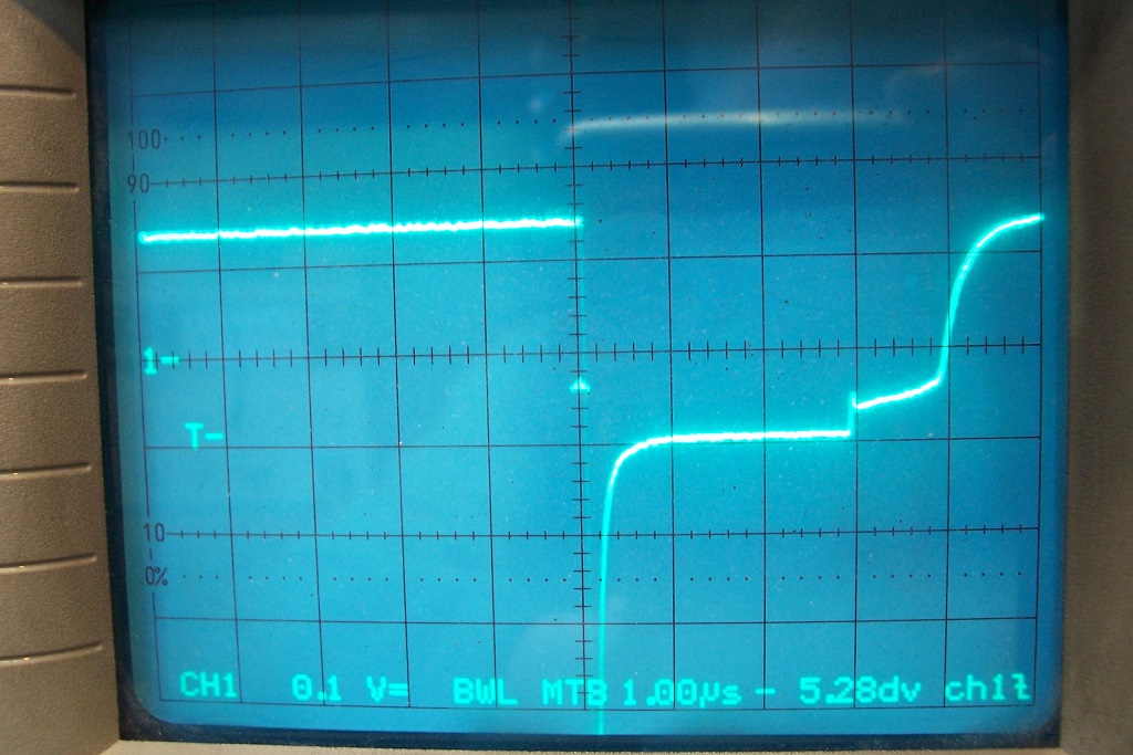
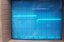
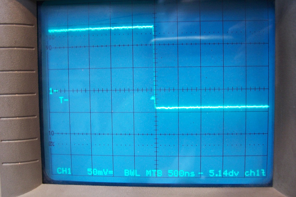
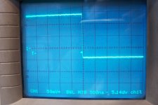
This is the Trr profile of the PY88: the recovery instant is at the center of the screen, and the horizontal center is the zero current.
The diode is switched from a forward current of 150mA (50mA/div) to a reverse bias of 300V. The only limiting measure is the 10ohm measuring shunt:
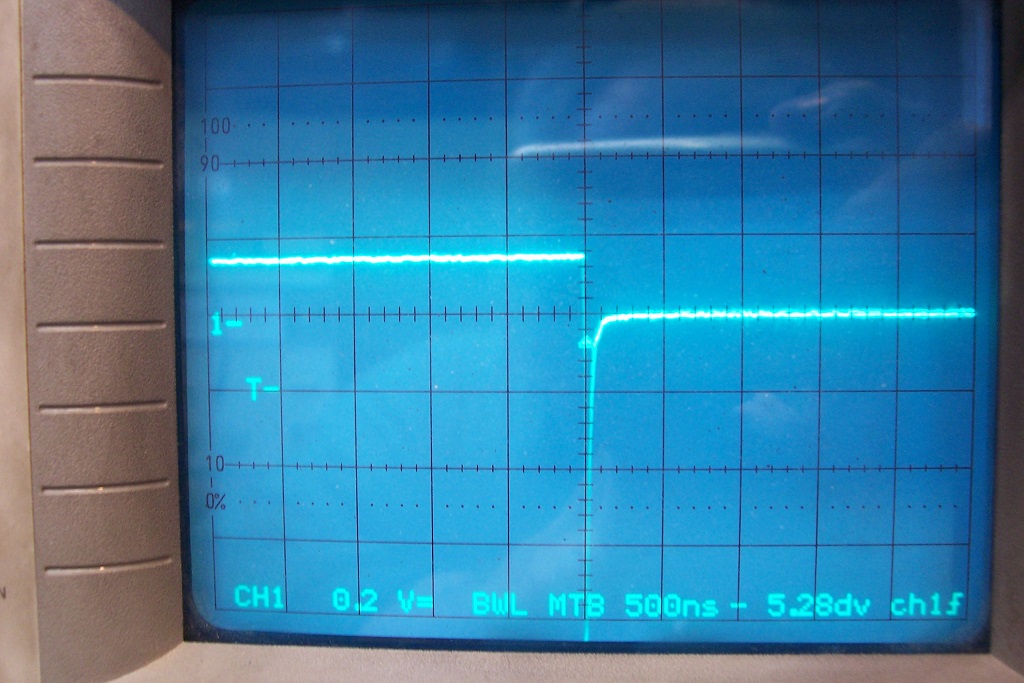
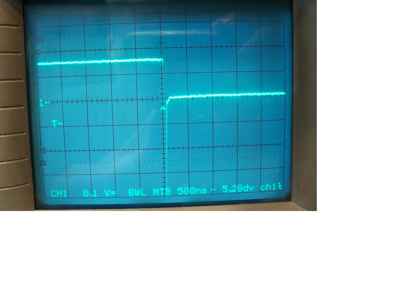
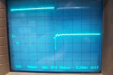
This is the Tfr profile, same conditions except the conduction starts in the center of the screen, and the Vf is negative (~12V) (the positive part is clamped by the 1N4148's to avoid saturating the scope's input):
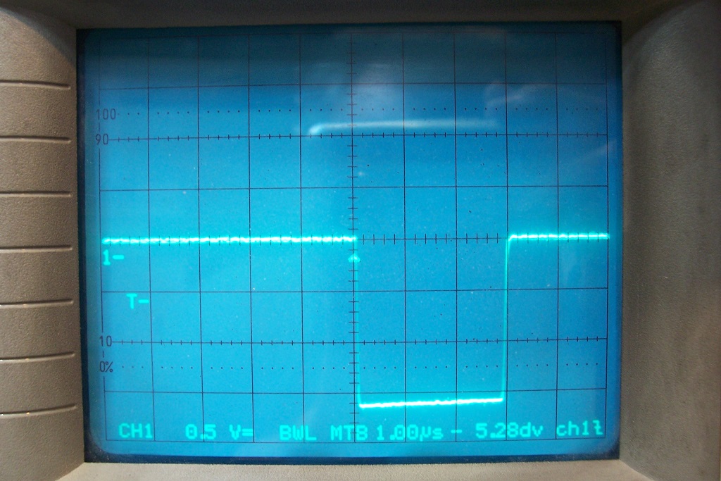
Both are practically spotless, and I suspect that the small overshoot is caused by parasitic couplings, not the PY88
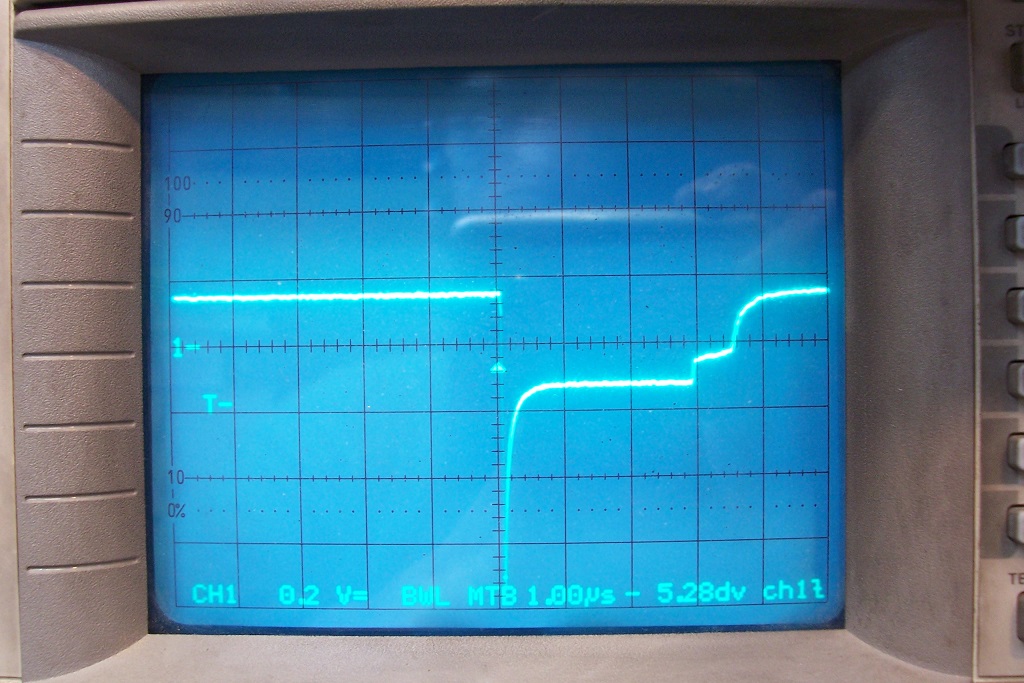
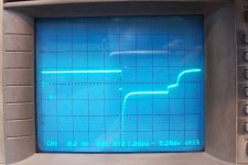
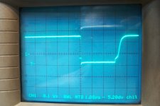
This is the Trr of the UF4007. Note the change of the vertical scale, which is not even sufficient to completely catch the huge recovery spike.
Tfr of the UF4007: a significant overvoltage is present:
For comparison, this is the Tfr of a BYV27-50: the 20x times lower Vrrm makes a huge difference. The result is almost perfect:
A BA159, another HV diode is in the same league as the UF4007, just worst:
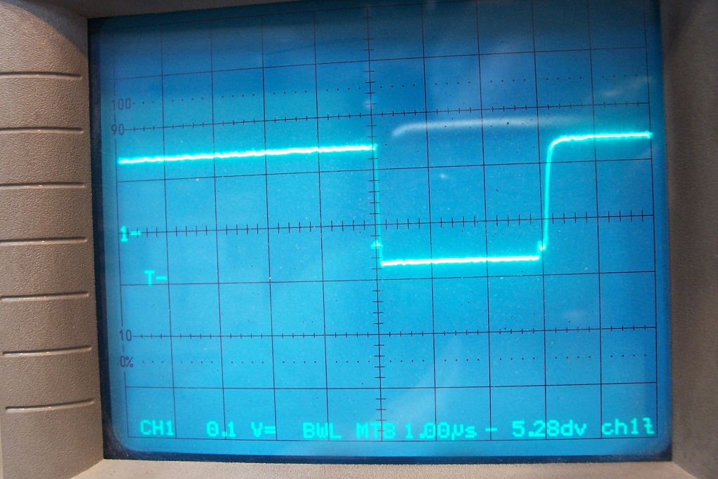
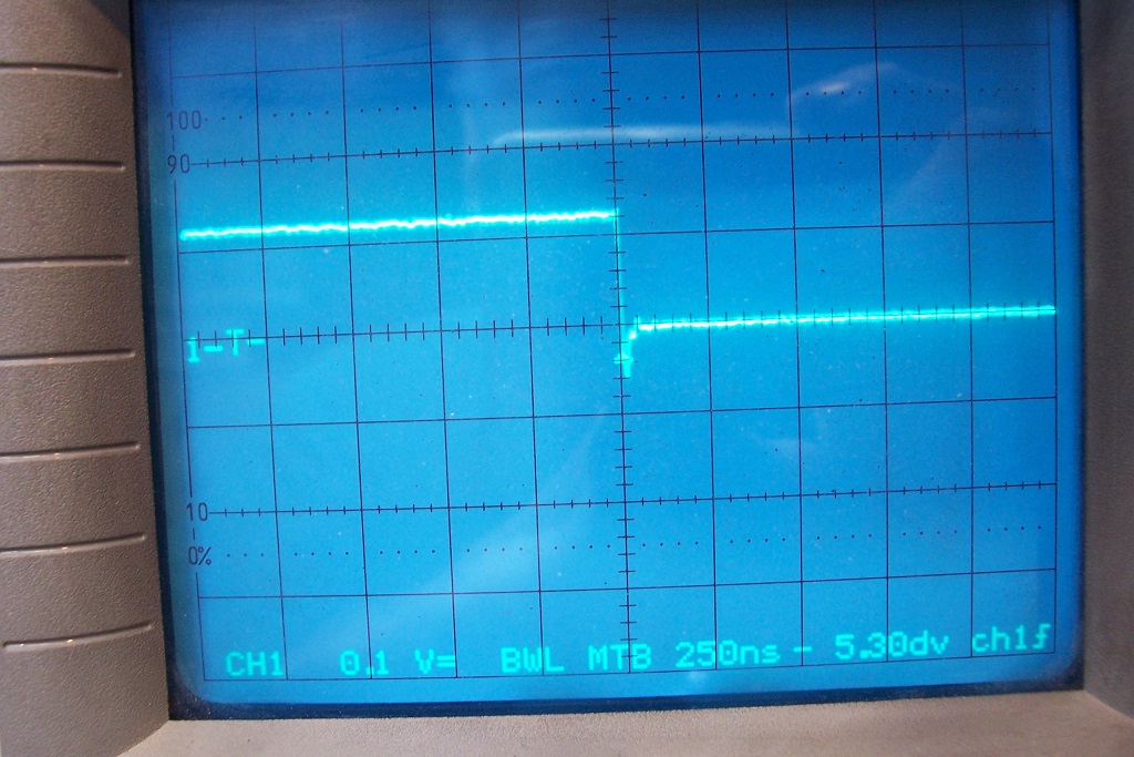
This is the Trr of an hyperfast diode, RHRP860:
And this is the Tfr:
-See next post, the 10 files limit is reached
Much better than the UF4007, but not as perfect as the PY88.
I do not have very high voltage schottky's, or SiC diodes.
I have other types of vacuum diodes, but I don't think the results will differ fundamentally
These are the test setups for the reverse and forward recovery behaviour.
They might look odd, and could probably be improved, but I didn't want to twist my mind too much for a one-off, and I wanted everything to be GND-referenced, to ease the connections and avoid potentially dangerous situations, both for the circuit and myself.
To minimize the dissipation, the circuit operates at a very low duty-cycle, and both version are using the same basic engine.
To get a good luminosity, the scope has to work in digital mode, which explains the lack of smoothness of the trace
This is the physical implementation of the Trr setup:
And this is the Tfr:
This is the Trr profile of the PY88: the recovery instant is at the center of the screen, and the horizontal center is the zero current.
The diode is switched from a forward current of 150mA (50mA/div) to a reverse bias of 300V. The only limiting measure is the 10ohm measuring shunt:
This is the Tfr profile, same conditions except the conduction starts in the center of the screen, and the Vf is negative (~12V) (the positive part is clamped by the 1N4148's to avoid saturating the scope's input):
Both are practically spotless, and I suspect that the small overshoot is caused by parasitic couplings, not the PY88
This is the Trr of the UF4007. Note the change of the vertical scale, which is not even sufficient to completely catch the huge recovery spike.
Tfr of the UF4007: a significant overvoltage is present:
For comparison, this is the Tfr of a BYV27-50: the 20x times lower Vrrm makes a huge difference. The result is almost perfect:
A BA159, another HV diode is in the same league as the UF4007, just worst:
This is the Trr of an hyperfast diode, RHRP860:
And this is the Tfr:
-See next post, the 10 files limit is reached
Much better than the UF4007, but not as perfect as the PY88.
I do not have very high voltage schottky's, or SiC diodes.
I have other types of vacuum diodes, but I don't think the results will differ fundamentally
Attachments
-
 DiodesTest0.png18 KB · Views: 487
 -
 DiodesTrrRHRP860.jpg324.2 KB · Views: 429
 -
 DiodesTfrBA159.jpg302.6 KB · Views: 405
 -
 DiodesTfrBYV27_50.jpg324.2 KB · Views: 426
 -
 DiodesTfrUF4007.jpg310 KB · Views: 418
 -
 DiodesTrrUF4007.jpg281.4 KB · Views: 411
 -
 DiodesTfrPY88.jpg297.8 KB · Views: 499
 -
 DiodesTrrPY88.jpg266.9 KB · Views: 427
 -
 DiodesTfrSetup.jpg449.7 KB · Views: 470
 -
 DiodesTrrSetup.jpg494 KB · Views: 458
Last edited:
I do not have very high voltage schottky's, or SiC diodes.
Is it possible to tweak your setup down to say - 40 or 60 Volts ?
Or maybe a series string of shottkys ?
I can tweak it to any voltage/current, but the comparison won't be exactly fair: I think my highest voltage schottky's are 100V, a third of the 300V I applied to the tube, but I can do it. Regarding Tfr, it will have no impact, but in general the attention is more focussed on the reverse recovery because of its higher impact in applications.
I think the most visible artifact/difference will be caused by the diode capacitance, significantly higher than for the tube.
I think the most visible artifact/difference will be caused by the diode capacitance, significantly higher than for the tube.
I have tested the 100V schottky: it is a B10100 made by ONsemi.
I have adjusted the reverse voltage to 100V, and If remains at 150mA.
This is the Trr:

A short, but large spike is visible. Almost certainly caused by the diode capacitance (~670pF).
For comparison, here is the PY88 again, in exactly the same conditions:
Now the Tfr behaviour:
This one is absolutely spotless.
For comparison, the same for the PY88, measured previously:

Thus, the reverse recovery behaviour of the tube remains vastly superior.
Note that the schottky is a relatively large one: 10A.
With a device having an If comparable to the PY88 (200mA for example), things would look a lot better, but the ~15pF of the PY88 (unheated) will be difficult to beat.
I have adjusted the reverse voltage to 100V, and If remains at 150mA.
This is the Trr:
A short, but large spike is visible. Almost certainly caused by the diode capacitance (~670pF).
For comparison, here is the PY88 again, in exactly the same conditions:
Now the Tfr behaviour:
This one is absolutely spotless.
For comparison, the same for the PY88, measured previously:
Thus, the reverse recovery behaviour of the tube remains vastly superior.
Note that the schottky is a relatively large one: 10A.
With a device having an If comparable to the PY88 (200mA for example), things would look a lot better, but the ~15pF of the PY88 (unheated) will be difficult to beat.
Attachments

Knowing tube theory from the big old books like Terman, Gray, Langford Smith, Reich and others, I already suspected that tubes must be quick recovery as there are only electrons moving in the vacuum and electrons are light weighth ans thus easy to move in the electric field between cathode and anode.
- Home
- Amplifiers
- Tubes / Valves
- Valve rectifier with high frequency AC