Gents,
I am trying to understand more about my 211 amp, and it has two 5u4GB rectifiers, and on the main transformer only 0 450v apparently no centre tap. ......I think...
Could it be a voltage doubler circuit maybe?
Is there a good way to see how the circuit works without a strip down, as a lot is out of sight.
Can I learn anything by taking some measurements from the 5u4 valve base etc.
211 is at ~1000v, so yeah I know it's dangerous poking around!
Just trying to learn things, no real reason other than initially trying to understand if my driver valves are diode or valve rectified.
Thanks,
100%
Ok - great!
Any circuit diagram that help explain this, and I might be able to check something by logic with some measurements on the valve base pins.
Can I assume the driver valves are taken off this in some way - I can't see any more diodes in the amp (from what is visible) other than the DC Heater on the 211.
Attachments

Maybe this explains it for you: Fundamentals Of Radio-valve Technique : Deketh J. : Free Download, Borrow, and Streaming : Internet Archive
Maybe this explains it for you: Fundamentals Of Radio-valve Technique : Deketh J. : Free Download, Borrow, and Streaming : Internet Archive
This is great - thanks,
saw this circuit, but not sure I understand it :-(
[/url]
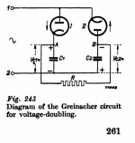
AC has both a positive and a negative sign each 1/50 second. On the positive cycle, the upper diode conducts and charges the upper capacitor. After that (0,01 second) period the lower diode charges the lower capacitor. So, each 0,02 seconds both caps receive their energy boost.
You could (should) connect an extra capacitor to the +E and -E terminals of #5 drawing. The bended line represents the cap negative terminal. In your amplifier you most likely find both cathodes in parallel for each 5U4, so they withstand higher loading currents.
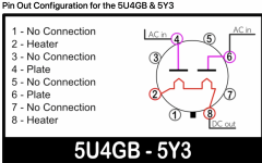
So can I assume for the pins on a 5u4GB like this picture then 2+8, and 4+6 are connected together and then on Page 261 like the image attached that rectifying valve I has pins 4+6 connected to AC+ve and on rectifying valve II that pins 2+8 are connected to AC+ve?
and what happens to the heater AC 5V; seems very confusing to me!!
(don't worry I am not going to blow myself up quite yet.....the only reason i want to find out is to understand my amplifier)
Thanks
Sorry this is all based on logic with no knowledge :-(
and what happens to the heater AC 5V; seems very confusing to me!!
(don't worry I am not going to blow myself up quite yet.....the only reason i want to find out is to understand my amplifier)
Thanks
Sorry this is all based on logic with no knowledge :-(
Attachments
it has two 5u4GB rectifiers, and on the main transformer only 0 450v
Can I learn anything by taking some measurements from the 5u4 valve base etc.
Because you have only one HV transformer and two rectifier tubes, there must be two separate 5V heater supplies for the rectifiers. The heater forms the cathode while the 'plate' connection forms the anode. They only conduct one way.
Because you have only one HV transformer and two rectifier tubes, there must be two separate 5V heater supplies for the rectifiers. The heater forms the cathode while the 'plate' connection forms the anode. They only conduct one way.
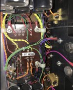
Yeah there are two 5V taps for the 5u4gb rectifiers.
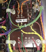
This is an image of the transformer, that I can see.
What I am trying to understand is where the 6C45 driver valves are getting their rectified B+ from.
Thanks so much 🙂
`
Attachments
Yeah there are two 5V taps for the 5u4gb rectifiers.
This is an image of the transformer, that I can see.
What I am trying to understand is where the 6C45 driver valves are getting their rectified B+ from.
Thanks so much 🙂
`
Just another idea - is it safe to simply remove the rectifying valves, which will leave the heaters working and then see if there is any B+ measured on the driver valves?
Will running a valve with heater and no B+cause any problems / damage generally?
just an idea
Hi tonescout,
No you will not cause any harm with the rectifiers 'pulled'.
The driver valves will have B+ straight away if there is a silicon rectifier in there, so a very quick test.
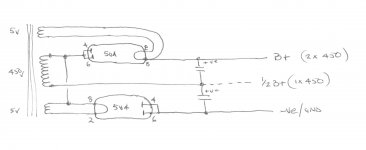
I suspect it will be much simpler, there are only 2 wires to the 450 ac volt transformer tap.
So the 211 B+ is from the doubler as you have found, the the driver B+ could be from the half way point in the supply (the junction of the first 2 smoothing caps) or conventionally from resistors dropping the total 900 volt B+.
Using the rectifier valves preserves the slow(ish) start for the 211 and drivers too.
No you will not cause any harm with the rectifiers 'pulled'.
The driver valves will have B+ straight away if there is a silicon rectifier in there, so a very quick test.
I suspect it will be much simpler, there are only 2 wires to the 450 ac volt transformer tap.
So the 211 B+ is from the doubler as you have found, the the driver B+ could be from the half way point in the supply (the junction of the first 2 smoothing caps) or conventionally from resistors dropping the total 900 volt B+.
Using the rectifier valves preserves the slow(ish) start for the 211 and drivers too.
Attachments
Hi tonescout,
No you will not cause any harm with the rectifiers 'pulled'.
The driver valves will have B+ straight away if there is a silicon rectifier in there, so a very quick test.
I suspect it will be much simpler, there are only 2 wires to the 450 ac volt transformer tap.
So the 211 B+ is from the doubler as you have found, the the driver B+ could be from the half way point in the supply (the junction of the first 2 smoothing caps) or conventionally from resistors dropping the total 900 volt B+.
Using the rectifier valves preserves the slow(ish) start for the 211 and drivers too.
Ok - great I will confirm.
The reason I am interested as I explained was to understand if diodes were used in the driver; and this is interesting to me because I changed my B+ diode rectification in my preamp based on a recommendation on SQ of a slightly strange approach....and I have been surprised at the benefits to the sound (these are now installed in my preamp B+)
A Guest Article from Mr. Shirokazu Yazaki: “My Adventure With My Old Marantz Model 7” Part 2. - Jeff's Place
30A diodes for a 30 mA supply - makes no sense BUT it does make a quite noticeable improvement in the sound
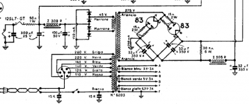
Here is a twin tube voltage doubler from a Geloso G275A, with seperate screen and plate supplies for 807s.
I think the trick with the 12SL7 heater supply to provide the bias is very neat.
I think the trick with the 12SL7 heater supply to provide the bias is very neat.
Attachments
Last edited:
Thanks so much,
- tried the rectfiers in and out, and yeah they are used in the B+ of the driver valve, likely as you say coming from one of the two 5U4GB rectifiers.
so no diode mods to consider!!
- tried the rectfiers in and out, and yeah they are used in the B+ of the driver valve, likely as you say coming from one of the two 5U4GB rectifiers.
so no diode mods to consider!!
This schematic may help in some way.
An externally hosted image should be here but it was not working when we last tested it.
If you combine voltage doubling with a direct heated rectifier like in the schematic in post #18, you have to be sure that the isolation of the 5V heater winding on the power transformer is good enough to withstand the high B+.
- Home
- Amplifiers
- Tubes / Valves
- Valve rectification question