
Looks like the same, right?
Still some hum but using scope don't see any AC oscillation. I connected the mu metal sheet covering the tube sockets to chassis ground waiting to lower the hum.
Lowered the hum but still some hum when volume pot starting to 1 to 2 o'clok. It seems needs more screening.
Link to youtube YouTube
Scope don't show ripple no other strange artifacts.
Maybe its a ground loop when connected to the system. Because the buzz in the video clip sounds strong enough and should have been captured by the scope.
Now I'm using a volume with switch ladder resistor of 100K so the source always see 100K, i'ts in a small box between the Itch and the preamp: could be the source of ground loop?
Salas Itch must be chassis grounded at the input?
Salas Itch must be chassis grounded at the input?
Attachments
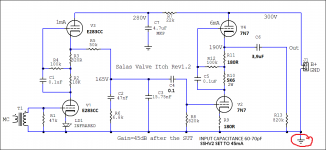
Not necessarily where the ground is shown, that's symbolic on the schematic. In high sensitivity valve builds we usually run a thick ground buss and we attach it to chassis at the input end.
You had a quiet Itch for years I think, is this a new build, or the same one developed a buzz?
You had a quiet Itch for years I think, is this a new build, or the same one developed a buzz?
Did you also change something in the ground wiring? Did you check with a scope that something hasn't failed in the B+ and its not ripple what you hear?
It started right after you changed the raw DC capacitors from 400uF to 1640uF? Maybe a rectification diode broke from the inrush current, or the regulator developed input side oscillation? Or a new high power on transient hammers it and breaks some of its parts? Check the whole DC chain for broken parts, or if you don't find any, for incompatibility. See what happens if with series resistor between the two 820uF, or with smaller raw capacitance, reg input connector film cap decoupling needed or not etc.
Alright for SQ explorations but over 4x increase in HV capacitance is a huge energy storage change in the PSU. Must had broken something.
PSU without load 450VDC
I'm sorry before PSU capcitance wasn't 400uF, was 840uF (2 BG 2 x 100uF each 200uF = 400uF + 1 Elna Cerafine 2 x 220uF = 440uF)
Also changed the two bridge rectifiers for DC heaters, attached pic.
I'm sorry before PSU capcitance wasn't 400uF, was 840uF (2 BG 2 x 100uF each 200uF = 400uF + 1 Elna Cerafine 2 x 220uF = 440uF)
Also changed the two bridge rectifiers for DC heaters, attached pic.
Attachments
![WP_20181006_007[1].jpg](/community/data/attachments/660/660779-77851eef5f7b110132db6bfe0e7b38a3.jpg?hash=d4Ue7197EQ)
Last edited:
Incoming GND from tonearm have to be connected only to chassis or also with signal GND?
BG & Cerafine 350VDC
Kemet 550VDC
BG & Cerafine 350VDC
Kemet 550VDC
So you changed some things to bigger then a buzz started. We now know its not a ground loop but ripple appeared on the B+. Mission: Find what has changed or broke between transformer output and reg DC output.
I will follow your advice, PSU rectifiers are OK right?
Measure the sections. DMM has diode check.
From Itch's input side signal GND buss bar connect a wire to chassis (only one ground wire point to chassis for the whole build). TT ground wire connected to the chassis also with a ground lug thumb screw or a 4mm banana plug. Must make contact to the metal, don't use insulators for the TT ground preamp's chassis terminal.
- Home
- Source & Line
- Analogue Source
- Valve Itch phono