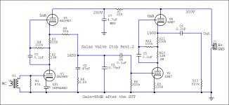
This is revision 1.2
Audio circuit rework. Mainly values.
All peripheral circuits remain the same.
THD at about 0.03% on nominal cart level, 2nd harmonic only.
Noise grass down to -86dBV@30Hz unweighted depending on input valve sample.
No perceptible harmonic noise when the SUT has a balanced primary and the cartridge is wired floating to it.
Only wide band random noise.
Curve is +/- 0.2dB 100Hz-15kHz including the SUT aberrations when R5,R6,C2,C3 are hand picked. R5=100K//100K. C3=15nF//750pF.
Suitable also for HOMC & MM sans SUT. Input overload: Beyond my oscilloscope's vertical capability at times 1.
Subjective impressions are enhanced vs. older version realizations.
Attachments

I have several questions:
-R2 18K 1W?
-For R11 I have Kiwame 2W and Shinkoh 1/2W, wich one do you prefer carbon or tantalum?
-In place of LD1 infrared I have 1N4148, is ok or have I to change for 1,9V-2V red LED?
TIA
-R2 18K 1W?
-For R11 I have Kiwame 2W and Shinkoh 1/2W, wich one do you prefer carbon or tantalum?
-In place of LD1 infrared I have 1N4148, is ok or have I to change for 1,9V-2V red LED?
TIA
That's good news!
Is there a chance for a PCB in the future?
Its been asked before, its true. It deserves it at a point since a bunch of p2p builders found it quite good already in only 4 common to get bottles giving 2 quiet enough channels. But no plans right now. Surely a board could make it a fast assembly, it does not carry much stuff concept wise, or anything particularly gimmicky to trim. Still putting it together p2p asks some expertise mainly bcs bottles are given distinct functions shared between channels. HV requires caution too, not best for potential novices messing too much with wiring. I will try to look into it in due time though.
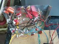
Rats nest alert
Hi Salas, All.
After a hiatus since 2011 im back with an Itch...
Just as I have spent the last week wiring up a test Itch, Salas tricks me with an update! I will have to order some new parts for rev 1.2 😉
I do need some help getting Rev 1.1 to work please.
I think the basic circuit is working ok, but hum is in the way. Underneath the hum it sounds promising. I know the grounding and wiring is far from optimal, but when i switch the power off the hum goes and the sound is clear for about 5 seconds. So I am guessing a issue with PSU side, the reg oscillating maybe?
I measured AC 4.6VAC output on the HV rectifier and 4.55VAC SSHV2 output.
I dont have a scope but am guessing this is not right.
I have SSHV2 260V 100VA tx, Measures 300VDC out, 35MA.
I have had to leave FOS and S+F wire links in place otherwise SSHV2 wont power up, so I believe I need to start here?
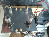
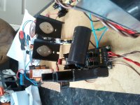
B+ S+F is connected to V4 pins 2&5, red wires in photos.
Grounds are split into left and right channels and connected to FOS, brown wires in photo.
Heaters at 6.1VDC and elevated tap at 151VDC, V1 pin5 & V2 pin8 grounded.
I had 4 6n2pev's and swapped them til the lowest V1 pin2 grid leakage, meter set to 200MV, pin2 = -165, pin7=-155.
No laughing at my lash up please 🙂
Hi Salas, All.
After a hiatus since 2011 im back with an Itch...
Just as I have spent the last week wiring up a test Itch, Salas tricks me with an update! I will have to order some new parts for rev 1.2 😉
I do need some help getting Rev 1.1 to work please.
I think the basic circuit is working ok, but hum is in the way. Underneath the hum it sounds promising. I know the grounding and wiring is far from optimal, but when i switch the power off the hum goes and the sound is clear for about 5 seconds. So I am guessing a issue with PSU side, the reg oscillating maybe?
I measured AC 4.6VAC output on the HV rectifier and 4.55VAC SSHV2 output.
I dont have a scope but am guessing this is not right.
I have SSHV2 260V 100VA tx, Measures 300VDC out, 35MA.
I have had to leave FOS and S+F wire links in place otherwise SSHV2 wont power up, so I believe I need to start here?
B+ S+F is connected to V4 pins 2&5, red wires in photos.
Grounds are split into left and right channels and connected to FOS, brown wires in photo.
Heaters at 6.1VDC and elevated tap at 151VDC, V1 pin5 & V2 pin8 grounded.
I had 4 6n2pev's and swapped them til the lowest V1 pin2 grid leakage, meter set to 200MV, pin2 = -165, pin7=-155.
No laughing at my lash up please 🙂
Attachments
Surely oscillating. Give it a physically smaller cap with short leads that fits the board much more closely first. With such wide open loop areas its difficult to build successfully in general, all kinds of problems may appear. You have a chance it basically works with a CRC passive PSU down to 300V and no reg for now. Add a downwards looking diode between V1's cathode and earth also. When you will get the new 1.2 values and IR LED its an opportunity you rebuild or at least rewire much tighter. Look back in Woodturner Fran's build for ideas.
P.S. About CRC just add a second same main filter cap and put a 5K6 2W between them (+) in series. Feed B+ to the main circuit from the last filter cap including GND sans reg.
Hi Salas / All,
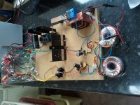
I removed the SSHV2 out of the equation, fitted diodes to V1 cathodes and did a rewire. Used a proper copper ground bus and following Frans grounding scheme minus the chassis ground resistor & diode bit.
Straight CRC passive PSU 294VDC B+ and the copper ground to the negative side of the PSU.
Much better, I have to turn the volume up to the point I hear valve hiss, and some hum, but the music would be very loud.
The next stage would be to reintroduce the SSHV2, I am a little confused with connecting FOS & S+F.
Do I connect S+F to V4 pins 2&5, and the copper ground bus to FOS with a link wire.
A couple of noob questions:
How do I check the 1.36mA and 3.5mA biasing of the valves?
How do I check channel balance?
It is sounding very good so far, cant wait to have it fully sorted 🙂
Many Thanks
Ian
Attachments
- Home
- Source & Line
- Analogue Source
- Valve Itch phono