It worked better for hum with the primary floating for ''balanced'' transfer, but it worked both ways.
I promised a few pics:
The layout might seem a little odd - the reason for the valves being in the centre is because I had the case already (with a 5th hole for a rectifier valve). The other thing is that the input transformers will most likely move from their current location to over the right hand side to place them far away as possible from the input AC wiring. I didn't read/think of putting the rectifiers and first cap in the transformer box.... so seeing as I've built each module I will leave it as it is unless there is a problem.
Both boxes are earthed, and I have a wire for signal ground from the phono box to the transformer box back to earth with back to back diodes//cap//15R power resistor. I need to organise a TT ground point on the phono box too....
Fran
An externally hosted image should be here but it was not working when we last tested it.
An externally hosted image should be here but it was not working when we last tested it.
An externally hosted image should be here but it was not working when we last tested it.
An externally hosted image should be here but it was not working when we last tested it.
The layout might seem a little odd - the reason for the valves being in the centre is because I had the case already (with a 5th hole for a rectifier valve). The other thing is that the input transformers will most likely move from their current location to over the right hand side to place them far away as possible from the input AC wiring. I didn't read/think of putting the rectifiers and first cap in the transformer box.... so seeing as I've built each module I will leave it as it is unless there is a problem.
Both boxes are earthed, and I have a wire for signal ground from the phono box to the transformer box back to earth with back to back diodes//cap//15R power resistor. I need to organise a TT ground point on the phono box too....
Fran
Looks fine, but try not to bring anything AC PSU feed inside the signal box. Unless you will get lucky.
Hi all,
I'm back from my holiday on which I indulged in days of live bluesy, rootsy music... lovely. ZZ Top was probably my highlight.
Woodturner, great to see significant progress! I'm yet to order many of the parts for my attempt.
I have a simple question as a new-comer to valve work, that I was not able to answer clearly through research. It relates to the valve sections and the relative envelopes that each one resides in. As far as my knowledge takes me, it is customary to use one valve envelope for two valve elements in a given channel. In the case of the Itch, the two valves in the input section (2x 6N2PEV) would reside in the one bottle. However, I think that this is not correct for the Itch as the voltage potential between the two valve sections is not safe to have within the one envelope... hence why the heater voltages must be referenced differently. Assuming this is the case, then the "upper tier" 6N2PEV of each L & R channels would be in one physical valve, as would the "lower tier" input valves of each channel... similarly for the upper and lower output valves.
Could someone please clarify which valve sections in the schematic can share the one valve bottle? If what I have described above is correct, can this influence crosstalk performance, or does the dividing grid in the 6N2PEV take care of this?
Regards,
Tani.
Last edited:
Thanks Salas,
That's what I thought. I'm thinking about layout at this stage so I figured I'd clear it up now as it could make a difference as to where I decide to place the inputs/outputs and so on.
Cheers.
That's what I thought. I'm thinking about layout at this stage so I figured I'd clear it up now as it could make a difference as to where I decide to place the inputs/outputs and so on.
Cheers.
I have most of the circuit wiring done now, I'm waiting on the K42Y coupling caps to arrive. I do have some other GE 0.68uF caps here that I know sound pretty good, so I might push them into service.
The RIAA caps are some nice matched mica/k42Y types from Russia via some Greek generosity (the mica measured 15.5nF, so a shade high). The output caps are some MKP types I had from a long time ago.
The pic is probably the worst quality one ever (phone camera) but give the idea at least.
Fran
The RIAA caps are some nice matched mica/k42Y types from Russia via some Greek generosity (the mica measured 15.5nF, so a shade high). The output caps are some MKP types I had from a long time ago.
The pic is probably the worst quality one ever (phone camera) but give the idea at least.
An externally hosted image should be here but it was not working when we last tested it.
Fran
+0.5nF on the Riaa HF cap can verge it to dull mind you. But wait to listen to it first because the cap meter might be happy. The interstage must not be bigger than 0.047u-0.1u also. The output cap lower limit depends on what load it has to couple, naturally. Thumbs up for the quick progress.
George also sent me K42Y 15nf - but recommended the mica type to try first. Happy to do that!
Tracking shows that the K42Y caps are in Russian customs. I'll search my parts drawer for something!!
Fran
Tracking shows that the K42Y caps are in Russian customs. I'll search my parts drawer for something!!
Fran
The Russian Mica is good in that position, but the value is very deterministic also. Will depend on the rest of your system tonality as well. How did you arrange the heaters PSUs?
2 x regulated supplies, one reg for the upper 6N8 + 6N2 wired in series, same for the lower.
I had plenty of spare 15VAC transformers to use... so went for the heaters in series.
*****************************************
2 separate listening rooms. One with stacked quads, 6SN7 aikido, ST70 running KT66s. Replinthed lenco L75 with roksan tabriz arm, benz L2 cart. Currently using DIY Ono for phono duty. Sound is big and bold and great for rock.
Second room, teres 260 TT with terminator style air bearing arm. DCB1 + (currently) tubecad EL84 triode PP amp and sachiko horns with fe206. Using pearl phonostage + lundahl step-ups and Zyx R50 cart. Sound more refined and polite but no less engaging.
Fran
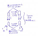
Don't know about series heaters, wasn't tested that way. Still those two tube types draw about same currents, hope they will share well. You lifted the upper bootstrap CCS valves of the mu follower totem as prescribed? Nice collection of listening stuff, especially the stacked Quads, you will have good discrimination of tone so to tune up parts, Riaa values, etc.
Sure, I know its a risk. I have read (only once) where someone said it didn't suit 6SN7 types - but broskie says no problem, plus I have used it in the aikido with no noise issues. We will see soon enough....
Heaters for upper pair will sit about 80V off gnd. Actual circuit is exactly as per itch rev1, heater supplies - exactly as per, except I don't have cap on the output of the regs yet (only 1.0uF PP), HV shunt is done as mentioned previously.
Couldn't find decent coupling caps in parts box...... grrr. Only things I have are panasonic (http://panasonic.com/industrial/includes/pdf/ABD0000CE47.pdf). I think I will fit them and I can then at least see if the circuit works OK. When the other caps arrive, I can swap them in easily. will be nice to see the difference too.
Fran
I have most of the circuit wiring done now, I'm waiting on the K42Y coupling caps to arrive. I do have some other GE 0.68uF caps here that I know sound pretty good, so I might push them into service.
The RIAA caps are some nice matched mica/k42Y types from Russia via some Greek generosity (the mica measured 15.5nF, so a shade high). The output caps are some MKP types I had from a long time ago.
The pic is probably the worst quality one ever (phone camera) but give the idea at least.
An externally hosted image should be here but it was not working when we last tested it.
Fran
Hi Fran
I am looking forward to hear your first impressions using the 15.5n micas.
i have been using 15.72n in that place and they really sound good... I could not find lower values yet.
Like your work... what type of wire are you using ?
Ricardo
SPC in teflon from navships on ebay.... eBay Shop - John's Silver Teflon Wire Shop: 26 AWG, 22 AWG, 24 AWG
George had marked the silver micas as 15.743, but when I measure them with my own meter they were 15.5. I suppose that is within the error range of my meter (not a fancy one).
Cascais: it is where I will be going on holidays this year!
George had marked the silver micas as 15.743, but when I measure them with my own meter they were 15.5. I suppose that is within the error range of my meter (not a fancy one).
Cascais: it is where I will be going on holidays this year!
Heaters for upper pair will sit about 80V off gnd. Actual circuit is exactly as per itch rev1, heater supplies - exactly as per, except I don't have cap on the output of the regs yet (only 1.0uF PP), HV shunt is done as mentioned previously.
Fran
The schematic Rev1 asks 1/2B+. So you need to divide near to 150V heater lift. The upper cathodes are at around 200V elevation. 80V isn't enough to bring the heaters in less than 100V distance to cathodes as the tubes spec asks.
Fran,
nice to see your progress!
Regarding the mica caps, I think that my LCR meter is more accurate, as I have cross checked it a couple of times. This is the one I use: TONGHUI DIGITAL HANDHELD LCR/LCZ/LCRZ METER,TH2821B,1K | eBay
Also the RIAA cap values you have now will let you experiment with values a bit, but when you find what you like, best is to replace with Teflon or good MKP's. Of course Ricardo and Merlin are the experts on this area!
George
SPC in teflon from navships on ebay.... eBay Shop - John's Silver Teflon Wire Shop: 26 AWG, 22 AWG, 24 AWG
George had marked the silver micas as 15.743, but when I measure them with my own meter they were 15.5. I suppose that is within the error range of my meter (not a fancy one).
Cascais: it is where I will be going on holidays this year!
Maybe your meter is not very acurate (These caps are also market 0.3%).
I just bought some 12.1nF CCT-1 and these are 0.5%... I will report after I try those. (I will trim them until 15.33n)
Thank you for the link.
When are you arriving to Cascais ? Maybe we could meet 🙂
Ricardo
Teflon film & aluminium foil 0.015uF 200V 1% 200V TexCap 43 or 400V 5% both 15$00 USD each, you can ask matched pairs to Mark.
Web: Surplus USA Film Capacitors Teflon Polycarbonate Polyester Polypropylene
E-mail: marko@33audio.com
Web: Surplus USA Film Capacitors Teflon Polycarbonate Polyester Polypropylene
E-mail: marko@33audio.com
- Home
- Source & Line
- Analogue Source
- Valve Itch phono