Hi Salas, thank you for posting this design, I've been looking for a tube phono amp that isn't too complicated and it looks like this could be a good one to build.
I have a question about the power supply. I already have a regulated power supply from a project that went in a different direction. It is the PS-1 kit from John Broskie on his glassware site. I would like to use it as the power supply for the Valve Itch. Do you think it would be suitable?
It can provide 50mA @ 300V for the B+ and 2.5A for the heater supply. Would it be a problem to use a single heater supply for all 4 tubes? I guess that I don't understand why there are 2 heater supplies in your design. I haven't looked at the documentation for the PS-1 in a while but I think the heater supply is floating at either 1/4 or 1/2 B+.
I can build a new supply if needed but its always nice to be able to use parts I already have.
The Broskie HVreg will certainly do its ripple kill job well, its analogous to the Mosfet Maida that was used in the first build. Later on you can experiment with the SSHV shunt reg too maybe. I recommend the revised schematic of the second build for the phono itself. There the upper tier tubes had elevated heaters at 1/2B+. The cathodes are sitting high. LM317T were used in those example builds and they are not trustworthy for above 1A constant for heaters in my experience (not LDO much heat), so 2 got used. That allowed to keep the lower tier tubes heaters separately fed and just grounded since there is no problem, their cathodes are very near relative to their cathodes for potential. And all was quiet. With just one heater reg you can't have separate heater elevation potentials, so 1/3B+ should keep the 6H2s just within spec bounds. I hope it will be as quiet.
Thanks for the input. your reply brings me to my next question. What do you mean by upper tier and lower tier tubes?
I apologize, most of my building experience has been using a pcb so I'm still trying to learn.
I apologize, most of my building experience has been using a pcb so I'm still trying to learn.
If you look at the schematic in post #31 there are two tubes near B+ and two tubes near ground. Since two heater regs on different elevation were used in those builds, they shared one 6H2 and one 6SN7 between channels for the upper side since each bottle's got two triodes, and one 6H2 & 6SN7 for the lower side.
Mods check
Salas
Can you glance at my scrawl attached just to make sure I have interpreted what you are saying correctly. I am planning on using the power shunt and hopefully have captured this correctly, plus as you advise will move some of the PSU circuitry to phono box as shown.
Secondly I have been looking at the heat sink requirements and trying to work out how many need in total and where. The 317's need them, without being too scientific about it these looked like they would be big enough? AAVID THERMALLOY | Semiconductors | Sockets and Heatsinks | Heat Sinks | Transistor Type Packages up to 48°C/W |6296B. They are rated 4.7 '/W whatever that means.....
I think there are some more heatsink requirements in the power shunt but not sure where or how big. Judging by the pics posted in this thread another one of the above sinks may be needed?
I am no expert and just need to be cautious that I am not being stupid!
Thanks for your excellent work.
Attachments
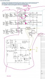
Your draft is correct, just don't use the 3300uF since your heater regs will be inside the phono, use 100uF. The 4.7C/W sinks for the 317s look big enough. Now for the B+ shunt reg: Give it 320-350V in and 300V out. Set it at 35mA. 10mA will go to both phono channels total. 20V-50V(in-out)x0.035=0.7-1.75W. Using the same type 4.7C/W sink for the input CCS Mosfet will up 8 degC from ambient mostly. Well. Things are different for the output Mosfet. Has to dissipate for 35-10=25-3=22mA (3mA is for the Jfet and BJT inside) times 300V. 6.6W constantly. That will up 31 degC on the 4.7W/C type. Think of a hot box inside (tubes, heater regs, closed) plus that. Maybe 70C or more in the end on that sink. No. At least double that sink's size for the IRF840. Example. Use 105C elcos for everything chemical caps inside the phono.
Thanks Silas. I am getting there just taking me a long time but then not having to rush is part of the beauty of this as a hobby 🙂. So much enjoyment from the anticipation of great things to come....
In the final 2.2uF cap what is the voltage? I am not competent enough to work this out and whilst I started building an Lt-spice model its going to be awhile until I have mastered the package!Went to Mikvous's place today to examine another Itch he made. With my Rev1 changes included.
Thanks
I would really like to be able to calculate this sort if thing myself Sp the supplementary question is how. I am not keen on just plugging numbers into software to come up with the answers as that does nit develop the same level of understanding. Anyone care to point me in the right direction for some good advice on how to improve my understanding.
In the final 2.2uF cap what is the voltage?
As rule of thumb the voltage of output cap should be greater than the p.s. voltage. If the Itch requires 300 V, better use a 400 V cap or greater.
Salas and others,
I'm collecting parts for the Itch (rev1 as in post #31 here) and I'd like to know which version of the HV shunt reg is recommended. In the SSHV thread the evolution/update link takes me to this.
Should I collect parts for this schematic or are there better options/updates to try?
I noted some changes for higher than 300v applications... what about a nominally 300v application such as the Itch? Would you recommend the higher voltage PNP noted in the linked post?
Regards,
Tani.
Last edited:
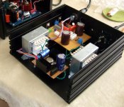
No looking further, that link leads you to the right one. Here is an example I made once for giving +HV & heaters juice to a tubes phono, taking the place of its stock tubes regulator box. Has the perfboard build shown in the link. 320VDCin will suffice for 300VDCout. Use 1N/UF4007 1000V PIV diodes in the rectifier bridge.
Attachments
Salas, What is the reasoning behind using one tube as input and one as load, as opposed to using one tube per channel?
Mu follower. Gives low Z output point, bootstrapped constant current source, insulates from PSU rail a bit. Upper valve has heater's lift, so can't be the same envelope.
Does it make a big difference? I've seen other designs where the cathode is lifted, but using 1/4 of B+ for the heater in a dual triode where one cathode is +4 and the other is something like +200. Just curious. I really don't know.
Last edited:
Mu follower is totem and with this B+ they can't share some middle ground same heater potential lift safely given their max spec. On the edge. So I went each envelope to its own ''floor''.
I'm having trouble sourcing a suitable transformer for the HV shunt. I pretty much need a 240v primary / 240v secondary as I'm aiming for the 300vdc reg output, and the original power supply sketch in this thread calls for 100VA.
A few questions:
- 100VA for the HV transformer seems large compared to what I am able to commonly find available. Is there a specific reason for this rating or can I safely go smaller without too greater sacrifice?
- Some power supply designs I've seen achieve low voltage for heaters and high voltage for B+ by using a step down Tx, say 12vac secondary, then a similar Tx wired in reverse to step the voltage back up. Would such a scheme work here (or anywhere)?
- Two 9vac transformers have been specified to supply the LM317 heater regs. Are the two needed as the regs don't share a common ground reference, or could 1 Tx be used so long as there are two rectifiers?
I can source cheap 96VA multiple output (6-12-18-24-30 Vac) transformers in metal enclosures with fuse and power lead. Could I use them in the configuration shown in the attached diagram?
Your help with the power supply is greatly appreciated as it is this item that is really slowing progress right now.
Regards,
Tani.
Attachments
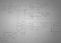
What you saw it was a description of how that PSU was made with transformers stuff that were available and not strictly a specification. Anything 30VA will be more than twice what a single 40mA CCS setting shunt reg will consume at those voltages. About transformer tricks I don't know much to guide you. Looks logical your plan, but I prefer others who have done such may comment. I just say use whatever easily available that will give you the proper voltages and currents. Use two 220K resistors in that schematic for 1/2B+ heaters lift in the newer phono circuit values changes. Fuse to the transformer's rating and be careful with high voltages.
I'm having trouble sourcing a suitable transformer for the HV shunt. I pretty much need a 240v primary / 240v secondary as I'm aiming for the 300vdc reg output, and the original power supply sketch in this thread calls for 100VA.
A few questions:
- 100VA for the HV transformer seems large compared to what I am able to commonly find available. Is there a specific reason for this rating or can I safely go smaller without too greater sacrifice?
- Some power supply designs I've seen achieve low voltage for heaters and high voltage for B+ by using a step down Tx, say 12vac secondary, then a similar Tx wired in reverse to step the voltage back up. Would such a scheme work here (or anywhere)?
- Two 9vac transformers have been specified to supply the LM317 heater regs. Are the two needed as the regs don't share a common ground reference, or could 1 Tx be used so long as there are two rectifiers?
I can source cheap 96VA multiple output (6-12-18-24-30 Vac) transformers in metal enclosures with fuse and power lead. Could I use them in the configuration shown in the attached diagram?
Your help with the power supply is greatly appreciated as it is this item that is really slowing progress right now.
Regards,
Tani.
Hi Tani
I have used 'back-back' transformers for valve projects and they work fine to get your HT.
To judge the final output voltage can be tricky, but more is generaly best, and OK for regulated circuits.
Think of the primary/secondary 'ratios' ie 240v/12v = 20:1
Then if you add a reversed 12v/240v = 1:20, you get back to 240v again.
If you calculate the ratios, you can work it out for any volt combination.
In my recent valve mic project I used a 9v & 15v, as the 'ratios' worked out good for my HT volts.
The thing to watch out for is the current rating of the 2nd transformers reversed windings.
The first transformer must have high enough VA & volts for heaters (I used 9v here, as this is fine for 317 style reg (12.69v @ smoothing caps).
The reversed transformers rating is slightly different, as 1amp/12v secondary rating, means primary is only rated at 50mA/240v etc.
So don't get caught out with a low rating there.
I try to allow for my actual wall voltage (230v),
Ratio of back-back transformers,
Diode drop (hardly worth considering at HT voltages),
Volts at my smoothing caps will be approx 1.41x final transformer ouput voltage.
This method has been disputed, but unless your running a difficult load, like an arc welder, it's always worked fine for me.
I believe Salas's shunt can take quite a high input, so I guess aim half way between this and the 'Itch' HT volts. BINGO.
Hope that makes sense.
Cheers
Simon
- Home
- Source & Line
- Analogue Source
- Valve Itch phono