Polystyrene, polypropylene or ceramic class 1 (for example NP0, also known as C0G) with a tolerance of 5 % or less (that is, at least twice as accurate as the inductor, so capacitance inaccuracies won't dominate). Don't use class 2 ceramic capacitors (X7R, X5R, X8R, Y5V, Z5U...), as they are inaccurate and nonlinear.
NP0 ceramic multilayer capacitors are readily available as SMDs. A working voltage of 25 V is more than enough.
For the resistors, metal film through-hole or thin film normal SMD or thin film/metal film MELF. Manually soldering MELF resistors is slightly more difficult than manually soldering normal SMD resistors because they tend to roll off the PCB.
Thanks for your usual helpfulness Marcel.
If I were using through hole parts your suggestions would be the route I would normally take (I'm getting good results with my DSC2 decoder which has polystyrene caps in the output section) . I've not been able to track down polystyrene caps in the correct values, (for example 3300pF is easy to find but 3000pF seem to be non-existent so that's immediately 10% out of tolerance) and, whilst polypropylene caps are available they tend to be very high voltage ratings and so physically large. I'm a lot less familiar with smd part types, especially capacitors, so it's good to get a steer on appropriate types.
Ray
There is nothing wrong with SMD NP0 / C0G multilayer capacitors and they are inexpensive as well (except for those with unusually high values). E24 values that are not in the E12 may be hard to find, but most E24 values can be made with two E12 capacitors in parallel or in series. For example, you can replace 3 nF with two times 1.5 nF in parallel.
I didn't sleep well last night and after making my previous post I had another search and found the necessary polystyrene caps on ebay (1% LCRs, 63V & 160V). I've ordered some so now I'll have a choice between them and smd components.
The 3nF cap wasn't the best example anyway as it's part of the LL1684 load rather than being a filter element so there will be a little more latitude.
The 3nF cap wasn't the best example anyway as it's part of the LL1684 load rather than being a filter element so there will be a little more latitude.
Last edited:
WIMA FKP 2 (German through-hole film-and-foil polypropylene capacitors with low self inductance) should also work quite well provided the tolerance is not too large (say 5 % or less). They are normally made in E6 values only.
The bling is progressing too...
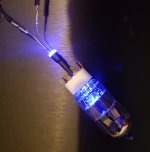
The light pipe that JPS suggested works well. The hole in the valve socket is a little large for the 3mm light pipe so I had to epoxy it in place. For now I have a 5mm purple LED attached to the light pipe with heat shring tubing but a friend has offered to 3D print some fittings so the arrangement is a bit stronger.
The light pipe that JPS suggested works well. The hole in the valve socket is a little large for the 3mm light pipe so I had to epoxy it in place. For now I have a 5mm purple LED attached to the light pipe with heat shring tubing but a friend has offered to 3D print some fittings so the arrangement is a bit stronger.
Attachments

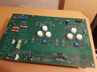
A bit more progress on the main PCB
Congrats Ray looks very good.
Bridging gaps too far
You have raced ahead there Ray and its looking amazing.
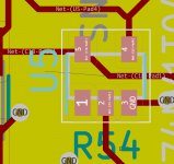
I have been slow to start due to (place excuse in here) however its the first time I doing SMD's but this is looking a little wrong to me.
Am I supposed to be bridging gaps this far....
You have raced ahead there Ray and its looking amazing.
I have been slow to start due to (place excuse in here) however its the first time I doing SMD's but this is looking a little wrong to me.
Am I supposed to be bridging gaps this far....
Attachments
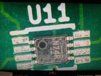
Am I supposed to be bridging gaps this far....
Hi Dan.
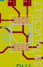
No. I think you have the wrong part. This is the part I ordered;
SN74LVC3G17DCTR Texas Instruments | Integrated Circuits (ICs) | DigiKey
Oh, that's a shame! Most SMD parts are available in different footprint-incompatible packages, I usually chose relatively large types to make soldering them a bit easier. The BOM list shows what footprint was used for what component. To make the mess complete, many packages have more than one name.
By the way, the BAS70 Schottky diodes come in different packages and in single, double, triple and quadruple versions. What you need is the single version in a SOT-23 package.
By the way, the BAS70 Schottky diodes come in different packages and in single, double, triple and quadruple versions. What you need is the single version in a SOT-23 package.
Dan, I have an updated version of the BOM with links to Digikey part numbers if it would help? So far just the smd parts and resistors but I'll add the caps shortly. Obviously there are a few parts that I've bought elsewhere.
Here's a link to the diodes Marcel mentioned in the previous post;
BAS70-00-E3-08 Vishay Semiconductor Diodes Division | Discrete Semiconductor Products | DigiKey
Here's a link to the diodes Marcel mentioned in the previous post;
BAS70-00-E3-08 Vishay Semiconductor Diodes Division | Discrete Semiconductor Products | DigiKey
Last edited:
Cheers Ray, I really appreciate that.
I am doing a double check on my parts also... Resistors and Caps seem to be ok its just the SMD. Tricky buggers!
I am doing a double check on my parts also... Resistors and Caps seem to be ok its just the SMD. Tricky buggers!
I have had a spot of luck and a bit of “its 30p buy both types”.
For all my tiredness I surprise myself and do not need to order more.
If anyone is thinking of making a sub miniature valve DAC then I have the SMD's for you.. 😉
For all my tiredness I surprise myself and do not need to order more.
If anyone is thinking of making a sub miniature valve DAC then I have the SMD's for you.. 😉
Hi Marcel. The build of my Valve AC is slowly progressing; mainly working on the power supplies at the moment.
As I mentioned before, I will use a Neurochrome Maida HV regulator, which is assembled and ready to test, for the B+ supply.
I'm undecided whether to go AC or DC for the valve filaments but have the parts to go either route. I'm leaning towards simple AC, at least to start with.
Regarding the 5V supply requirement, do you know the current that the L4940V5 device has to supply? I ask because I have a couple of 5V LDO low noise voltage regulators available and I would like to try them, however, the best one is only good for 500mA though (and the other 1A). I've installed a socket on the main board so I can substitute different regulators. I guess I could get an estimate of the current from the schematic and various datasheets but that sounds a bit tedious so I thought I would ask first.
Thanks
Hi Ray, my best estimate for the DSD-only valve DAC is about 100 mA at DSD512 rates, with a clock at the double frequency that is divided off locally (worst case). It's only an estimate, so it is nice that you have some extra margin.
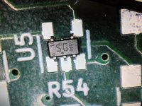
With confidence knocked on these SMD’s, I'm almost sure this is the correct part as there are only two variations and one is the wrong foot print. its U5 74LV1T04 of which I have the GWH variation.
Ray do you have that Digikey check list?
One other question:
The valve mounts although I have the board mount sockets what would be the detriment of abstracting them from the board with 10mm of wire. The benefits would be that I can mount them on an aluminium plate
Ray do you have that Digikey check list?
One other question:
The valve mounts although I have the board mount sockets what would be the detriment of abstracting them from the board with 10mm of wire. The benefits would be that I can mount them on an aluminium plate
Attachments
The valve mounts although I have the board mount sockets what would be the detriment of abstracting them from the board with 10mm of wire. The benefits would be that I can mount them on an aluminium plate
Probably an increase in noise floor by an amount I can't predict. My gut feeling is that it will only be a small amount, since 10 mm is not that long compared to the wiring that is already there inside the sockets and inside the valves.
- Home
- Source & Line
- Digital Line Level
- Valve DAC from Linear Audio volume 13