I frequently run parallel triodes. A less than perfect match is very musical.
I've noticed the noise floor is lower too.
I've noticed the noise floor is lower too.
Input stage:
Two 1500 Ohm will work as good as two 1640 Ohms (similar operating point).
But depending on how well the triodes match, connecting a resistor between the two cathodes may or may not change the sound versus a single triode. That resistor between the two cathodes will not increase the match of the two triodes, but it could decrease the match of currents between the two triodes.
Are you also asking about the next stage (phase splitter)?
That has completely different issues and hints for best operation.
Thanks.
Last edited:
I frequently run parallel triodes. A less than perfect match is very musical.
I've noticed the noise floor is lower too.
yes, thats like domino FX because one thing leads to another and in the end alot of "rZohms/noise goes thru the ground" <--- lame pun and you can always use two components of same value instead of one to rematch the operation point... this also give less than 0.001dividedby0.001 less heat and less heat noise and decrease the risk of failure indicating a mismatch on the sector's part
and no matter if its 000.1dividedby0.001 or 0.0001/0.0001, all of that equals to 1 whole, wich means there will be one more improvement in something to pile up in favour of the next century's generation of tube amps for that nasty brats to fiddle with!
but there wont be a next century without good music, mankind would endup killing themselves due to boringness, or do stupid things and fry the planet, stuff like that... but dont worry, i'm working on it, we're all together in this one, m8's
Input stage:
Two 1500 Ohm will work as good as two 1640 Ohms (similar operating point).
But depending on how well the triodes match, connecting a resistor between the two cathodes may or may not change the sound versus a single triode. That resistor between the two cathodes will not increase the match of the two triodes, but it could decrease the match of currents between the two triodes.
Are you also asking about the next stage (phase splitter)?
That has completely different issues and hints for best operation.
Thanks.
if you want to take part on it be welcome, but i didnt had gone that far ambicious, to think about
why not? let's go then... open your mind to us and let all this madness flow into a masterpiece even more badass than it was thought to be!
Last edited:
Start with a phase splitter that has a resistor used as a pseudo current sink in the two cathodes circuit. That causes an imperfection of the balance of the two phase's amplitudes. That is due to the imperfect current sink (a resistor, not anywhere near to a near infinite impedance).
When using a resistor current sink, in order to match the amplitudes of the two output phases, the plate loads will be different resistances. The tube that has the driven grid will have a lower resistance plate resistor, and the tube that has its grid held to 0VAC (signal ground), usually with a capacitor to ground, will need a higher resistance plate resistor.
What happens if you do not properly adjust the two plate resistor values?
You get 2nd harmonic distortion.
A lot of Hi Fi purists might not like that (at least not like the idea), but another Hi Fi person might like a little 2nd harmonic distortion.
But I bet a lot of Guitar people would like that 2nd harmonic distortion.
A Hi Fi purist might like the idea of using a real good current sink (not a resistor), and then want perfectly matched plate load resistors. That would give perfectly matched amplitudes. It would also null out the 2nd harmonic distortion.
Then you can tube-roll, and still have matched amplitudes, and still null out the 2nd harmonic distortion, with no adjustment needed.
Slick, if that is the way you want it.
For a simple guitar circuit, use a cathode resistor current sink, and use matched plate load resistors. You will get 2nd harmonic distortion, if that is what you want.
It does not get any simpler than that.
Depending on the person, a little 2nd harmonic is a good thing, a lot of 2nd harmonic is a good thing, or no 2nd harmonic is a good thing.
Last edited:
I too believe in engineering, not gambling. This is true whether we're talking Hi-Fi or guitar amplifier. 🙂In Hi Fi I consider the best policy is to keep from gambling.
I agree completely. But this same approach simply won't work for electric guitar amplifiers! The trouble is that a solid-body electric guitar plugged into a Hi-Fi audio system sounds absolutely terrible. It-hurts-your-ears terrible!...Hi Fi amp...RC coupling...turns it up so high as to draw grid current...Either turn the volume down, or get a more powerful amp. Otherwise, it is not Hi Fi.
If you take a mono Hi-Fi system, rip out and throw away the tweeter, and thus limit treble response to no more than 5 kHz, the electric guitar still sounds terrible, but at least it won't stab you in the ears. However, Les Paul himself seems to have been the last electric guitarist who actually liked this "ultra clean" guitar tone, in 1951, now nearly 70 years ago: YouTube
Ten years later, in 1961, Buddy Guy was deliberately and intentionally turning up his guitar amp until it was quite audibly distorting - just listen to the opening lick: YouTube
Five years after that (1966), Eric Clapton was one of the 8guitarists who had discovered that if you heavily overdrive a tube guitar amp, you not only get much more sustain out of the guitar, it also sounds like an entirely different instrument. Compare the opening licks of "All Your Love" with the sounds Les Paul was making only fifteen years earlier: YouTube
Fast-forward another 8 years to 1974; here's Deep Purple's "Burn", with no trace of a clean guitar tone to be heard anywhere: YouTube
Now listen to the amount of distortion used by Gun's n Roses guitarist Slash, in 1987, thirteen years later, with one of his typical catchy signature riffs in their big hit "Sweet Child of Mine": YouTube
Skip to 2003, and here's Evanescence's "Going Under". The guitars are now so heavily distorted that they sound like power tools grinding on a tin roof to me: https://www.youtube.com/watch?v=CdhqVtpR2ts
As you can see, the sound of guitars in popular music has changed tremendously over the decades. In 1950, a valve guitar amp was basically a cost-reduced, mono, Hi-Fi amp with no tweeter. By 2000, a valve guitar amp was designed to churn out a thunderous grinding noise that bore no resemblance at all to the sounds Les Paul was making in 1951.
So, for 99% of guitarists today, there is no question at all of keeping the signal level down below the onset of grid current flow. Instead, the opposite is closer to reality: chances are the amplifier will be operated with multiple valve stages deep into grid-current territory.
You mentioned the need for a bigger Hi-Fi amp if grid current flow occurred. With valve guitar amps, the opposite is frequently true: in order to get deep into distortion without becoming so loud as to attract the police, guitarists have been moving to lower and lower powered guitar amps, especially for home use.
The last valve guitar amp I prototyped had a maximum output power of a whopping 200 milliwatts. I could overdrive it in my apartment without annoying my neighbours much - but even 200 mW is pretty loud when you feed it into a guitar speaker with a sensitivity of 95 dB@1W@1m!
-Gnobuddy
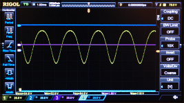
The attached image shows the amount of distortion I needed to get a good clean guitar tone from a low-powered valve guitar amp. 😱But I bet a lot of Guitar people would like that 2nd harmonic distortion.
This is somewhere between 10% and 20% THD, I estimate. And with a guitar plugged in, it doesn't sound distorted, it sounds clean.
This is an oscilloscope capture I took after many, many hours of calculations and test-bench tweaking finally got me a great clean tone out of my little two-watt 6AK6 push-pull guitar amp.
The thing is, any halfway-decent solid-state amp beats the pants off any tube Hi-Fi amp when it comes to low distortion, which is why I myself have no interest in valve Hi-Fi. (But I recognize other people's right to do silly things for no good reason. 😀 )A Hi Fi purist might like the idea of using a real good current sink (not a resistor), and then want perfectly matched plate load resistors.
-Gnobuddy
Attachments
The old marketing "distortion spec wars" created the need to use giant gobs of global negative feedback around the solid state amplifiers.
I had a friend that had a Hi Fi solid state amp that had glowing reviews. It had super low distortion specs (when loaded by a non-inductive power resistor).
When he connected the amp to his loudspeakers it had real problems, it oscillated and burned out his tweeters. So much for that.
A manufacturer in Portland Oregon had a wonderful solid state amp with lots of negative feedback (super low distortion on a non-inductive load power resistor).
When the production started, and amps went out the door, people started connecting them to . . . you guessed it, loudspeakers.
There was close to a 100% return rate.
The next amplifier design from that company used far less negative feedback, had moderate distortion, and actually worked and sounded good on loudspeakers.
There were a couple of research papers, one from Mattie Otala, I can not remember the other researcher's name. They gave us invaluable information about Transient Intermodulation Distortion, and related that to the amount of negative feedback used in amplifiers.
Just food for thought.
There was an event when a local vacuum tube club was invited to a listening session at a local Hi Fi shop. The opportunity was to hear the Hi Fi shop's latest greatest solid state amplifier.
Someone brought a Dyna Stereo 70 tube amp. A soldering iron, 10 minutes to modify the amp, and guess what . . .
When they compared the Super solid state amp to the easily modified tube amp, there was a general agreement that the tube amp sounded better (whether "sounds better" actually is better is not the point).
But it is true, that the local vacuum tube club was Never invited back to that Hi Fi store.
James Watt started it, when he invented the unit called horsepower, and began to apply it to his steam engines! 😀BUT i must persuade you into considering not using horses as a comparison because a horse is alive...
You like a lot of distortion, I know. And if I turn my Katana 50 gain up too far, the sound becomes gritty and unpleasant. So I can very well imagine that you might not like this amplifier....I tested the boss katana...
But: turn down the gain, and the Katana 50 produces better "valvey" clean tones than my real tube Fender '65 Princeton Reverb reissue does...and I use clean tone 99% of the time.
AND the Katana works very well at apartment-safe volumes; my PRRI sounds thin and nasty when you turn it down that much.
AND the Katana works very well at the loudest volumes I ever want: I used it at an outdoor jam on a local farm in the summer of 2019, and to my surprise, it was more than loud enough.
AND it works very well as an acoustic guitar amplifier for my electro-acoustic guitars.
Overall, to my own surprise, I think the Katana 50 is the best guitar amp I've ever owned - better than my two Fender valve amps, and better than the one or two DIY valve amps I've built myself.
-Gnobuddy
Not sure what you mean by "super low", but for the spec-driven, Douglas Self has provided designs that reach 0.005% THD, while being perfectly stable.It had super low distortion specs...oscillated and burned out his tweeters.
This low a distortion is ridiculously unnecessary, however. All you need to have THD far below audibility is less than 0.1% THD, and there are thousands of perfectly stable solid-state amps that will meet and exceed that spec.
The other "researcher" is a diyAudio member, and still posts in various threads on one of the subforums I avoid....Mattie Otala...the other researcher...
TID was the most absurd nonsense ever to briefly flare into popularity, during a decade filled with plenty of superstitious beliefs, ranging from spoon-bending telekinetics to levitating meditators. TID has since disappeared from audio engineering circles, because it was nonsense. However, of course, it lives on on the Internet, just like cold fusion and flat-earthers.
The fact is that TID was not a new discovery - it was something well known for a hundred years in the field of control systems and control system theory; namely, if you put too fast a step input into a feedback system, it will misbehave. The solution is trivial: don't put ridiculously fast signals into the amplifier!
This is trivially easy to do: put a lowpass filter with a corner frequency well above 20 kHz, but well below radio frequencies, in front of the amp. Don't feed video signals that are a hundred times faster than any actual audio signal into an audio amp, and all will be well!
This is why I like valves in guitar amps: they make an otherwise boring musical instrument sound better. (And I say this as a person who has spent 35 years learning and practicing to become a better guitarist.) Such an amp is absolutely NOT Hi-Fi, but rather, a timbre-modifier that can be considered a part of the electric guitar itself. It is not intended to accurately reproduce a sound at all...."sounds better"...
But Hi-Fi is a contraction of High Fidelity, meaning, *accurately faithful* to the original signal. A Hi-Fi amp should have no sound of its own - it should accurately reproduce the input signal. An amp that makes something sound better can only do so by adding audible amounts of distortion, and by definition, that is not high fidelity - it's not accurately reproducing the original signal.
For lack of a better term, I call valve amps that ladle up lots of syrupy distortion "My-Fi", i.e. they mangle the audio signal to suit the listener's personal tastes. Nothing wrong with that, of course, it's like the people who pour ketchup on their steak because they don't like the taste of steak itself. But I don't see how one can confuse a syrupy-distorting amplifier with high fidelity.
I don't think we are about to change each other's opinions, so I'll leave it at that. 🙂
-Gnobuddy
Start with a phase splitter that has a resistor used as a pseudo current sink in the two cathodes circuit. That causes an imperfection of the balance of the two phase's amplitudes. That is due to the imperfect current sink (a resistor, not anywhere near to a near infinite impedance).
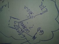
i'av attached sketches of what my mind could understand by what you've posted;
since i dont know which value of a resistor is considered a 'resistor-level' for you, lets praise a la Motörhead's Ace Of Spades and start the gambles to try to squeeze information from you:
this time my biggest and farthest bet goes to my pair of 6.8M and 10M... if they are too far from the bullseye, then lets fuse them into some parallel reduction to about 4M, but wait! it gets complicated now... i've got some stuff of about 220k, 68k, 82k, 120k, 33k, 22k, 10k, 1.2k and some big wirewound 5 watters, the green stuff, ranging from 125-270 and 470r
thanks
EDIT: i dont know what a current sink is, goodzilla says things with transistors and diodes, i saddened when had toughts of including silicon (i love crystals... quartz ones) but not in my signal chain... they are cool for optixs, no pun
i'll have the accept the energy of silicon in my power supply until i feel in the mood to rip off the diodes of this amp and install ez81 and kill/omit some cans not needed to keep the diode-tube steady&smooth
Attachments

Last edited:
The attached image shows the amount of distortion I needed to get a good clean guitar tone from a low-powered valve guitar amp. 😱
-Gnobuddy
beautiful shape, such a joy as the lines of midcut from your adaptatio'f tha voight ts
i kinda want to preserve the wave without clipping it i dont know of exist unclipped distortion, but maybe adding harmonic of beautiful 2nds or something natural sounding will be great, and this is importante:
the angle of the curves at every coordinate that the line exist in the graphic must favour the pi perfect inclination to form a 360 full circle sized the same as the peak amplitude thus farthening the center of the peaks horizontally proportional to its lenght, been macarroni-piled up to the oscillations ratio to correspond to the frequency number, so distorting the speed perception without adding a speed pitch effect 😀 it PhAtTenS the sound and make it ghostly chewy (my wife call bubblegum chewy when the tone is kinda... you know, faithful to not exceed its parameters of harshbeast)
meanie 😛James Watt started it, when he invented the unit called horsepower, and began to apply it to his steam engines! 😀
yeeaah u meanie, distortion-wise, i know you know 😉You like a lot of distortion, I know. And if I turn my Katana 50 gain up too far, the sound becomes gritty and unpleasant. So I can very well imagine that you might not like this amplifier.
and i know that you know dat i kno 😀
Overall, to my own surprise, I think the Katana 50 is the best guitar amp I've ever owned - better than my two Fender valve amps, and better than the one or two DIY valve amps I've built myself.
ok ok friendie, in respect to you then i'll buy this stuff to have some fun with it for experimental purposes, but im more a fulltone guy than using boss... i heard their roland choruses are superb is one SS amp in my extreme musthave list, another is the dreadful FENDER DELUXE 85... i had one but wasnt full original, plus it failed and the repairshop took 6 months to give me it back sounded no-good that i easily traded away that thing to never look back, carrying the faith to aquire a decent and original one someday (maybe recapped is acceptable, dang! meanie cans!)
-Gnobuddy[/QUOTE]
Yes, I understand that you both like the distortion in a guitar amp.
By all means, draw grid current, without a driver that can linearly drive that current.
Gets you what you want.
Don't use a driver that some Hi Fi types use, it will drive grid current at very low distortion.
By all means, draw grid current, without a driver that can linearly drive that current.
Gets you what you want.
Don't use a driver that some Hi Fi types use, it will drive grid current at very low distortion.
Some day I do want to build a guitar amp using MOSFET source-followers to drive the output valves into AB2....a driver that...will drive grid current at very low distortion...
Tubelab (George) has demonstrated the ability to get 30 - 45 watts (!!) RMS out of a pair of ancient and unloved one-dollar radio output valves in PP class AB2, valves that normally struggle to put out a couple of watts in the original radio design (SE, pure class A).
I should hasten to add that this is a man who knows what he's doing; he's got the measured data to show it works, and that it works while keeping anode dissipation to an entirely reasonable level.
It's hard to resist the temptation to wrestle a quart out of a pint pot, which is why I want to build something along these lines. At the same time, the 15-watt valve guitar amps I own are too bloody loud to use, so my need for a 30 watt valve guitar amp is questionable!
-Gnobuddy
okay, but is the drawing of the so called current sink boostrap into the pi cathodes correct?
what value is the so called resistor-level of resistance?
i kinda dont care if its seen as distortion or not aslong as the sound matches with what i want: beautiful roundwaves with no clipping <3
but it doesnt matter to discuss it aslong as i can put this beast to test after finishing
only this questions left thxuall
Trust me, you do NOT want current sinks in your guitar amp phase splitter.okay, but is the drawing of the so called current sink boostrap into the pi cathodes correct?
The long tailed pair phase splitter has exactly the type of distortion you want - smooth and rounded - and it contributes a lot to the sound of the guitar amp. In my opinion, don't change anything in the PI - build it just like the schematic you posted in your post #1 on this thread.
Something was misunderstood between you and 6A3sUMMER - there is no such thing as resistor-level of resistance.what value is the so called resistor-level of resistance?

Again, my opinion: don't change anything in the PI! Build it just like your schematic in your first post on this thread.only this questions left thx u all
-Gnobuddy
Trust me, you do NOT want current sinks in your guitar amp phase splitter.
The long tailed pair phase splitter has exactly the type of distortion you want - smooth and rounded - and it contributes a lot to the sound of the guitar amp. In my opinion, don't change anything in the PI - build it just like the schematic you posted in your post #1 on this thread.
Something was misunderstood between you and 6A3sUMMER - there is no such thing as resistor-level of resistance.
Again, my opinion: don't change anything in the PI! Build it just like your schematic in your first post on this thread.
-Gnobuddy
okie-dooky i'll stick to your advice!!
on the parallel v1 tho i'll do the bootstrap thingy because our friend 6a3 had a great idea to tame the problems i mentioned
but ltpi will be left untouched
thanks you all for helping, i hope somehow the time you all invested to help me turns into good things for you because i believe only my gratitude and appreciation for yerall help isnt enough to pay for the valuable knowledge yall shared
but all i have to give now is my thanks!
cheers from BRASIL ;D
Glad to help when I can!...pay for the valuable knowledge...
I really don't understand people who want to hoard their knowledge and keep it to themselves. I've always felt that the best thing to do with knowledge is to share it, as my small way of trying to make other people's lives better. 🙂
-Gnobuddy
- Home
- Amplifiers
- Tubes / Valves
- values for parallel triodes into LTPI