Allright, a power supply board without bleeders might not have been the best idea.
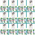
Here are the gerbers for the improved version.
Amazing thread.
Thanks a lot for all these nice design.
BR
Eric
Re: Simple phase splitter boards Post #43
I think it would be a worthwhile improvement to provide for a grid stopper for V1B and V2B (the concertina phase splitters). Can that be added in general, or is that a special request?
Thanks for this, by the way. Very much appreciated.
--
These are very simple phase splitter boards, I imagined these used with 6N1P or 6N2P. These are roughly equivalent* to the 6SN7 and 6SL7 in 9 pin noval package*
These should be workable boards, if you need a tad bit more gain you can decouple the first tubes cathode.
Sockets are mirrored, with a 3mm hole in the centres of the sockets to mark out the holes on the chassis.
PM if you want me to make slight alterations.
*Not entirely electrical similar but made as a miniaturized replacement in new equipment.
I think it would be a worthwhile improvement to provide for a grid stopper for V1B and V2B (the concertina phase splitters). Can that be added in general, or is that a special request?
Thanks for this, by the way. Very much appreciated.
--
Last edited:
I dont think you need that grid stopper there, unless running HF tubes. YMMV through.
The cap footprint is rather small but was made with 10-47nF radial caps in mind.
Its a special request im afraid, but it wont be an enormous amount.
The cap footprint is rather small but was made with 10-47nF radial caps in mind.
Its a special request im afraid, but it wont be an enormous amount.
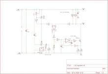
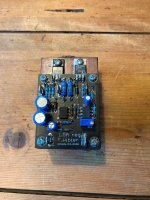
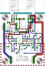
1.5A DHT regulator.
This is a little regulator i developed for low noise DC for tube filaments for types like the 300B and 6B4G.
Specs:
Dropout voltage : 4V worst case scenario. If dropout occurs the regulator will maintain output voltage down to 1V dropout, its just noise will be higherbecause the LM337 will be operating in dropout conditions.
Output voltage : Adjustable between 2.5 and 7.5V higher is possible
output current : 1.5A continuous, about 2A short circuit
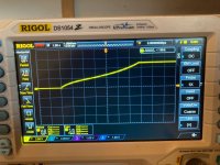
Output noise : hard to measure, its below the noise floor of my instruments. There is some popcorn noise on my scope but its low amplitude.
Input voltage : 6.5-30V with no troubles, if the input electrolytic is rated for 35V
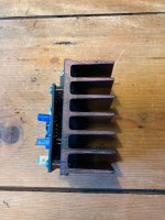
Features: Slow start of filaments, thermal overload protection and short circuit proof on a sizeable heat sink up to 7.5V output voltage. The Current source is hard limited to 2A of output current
It works really well, and i'm proud of the result. but the topic i opened on the design derailed. For which i myself am largely to blame.
Improvements
You can allways try a different opamp, im in the process of soldering up a new test board equipted with NE5332 to see if that gets the noisefloor down further, because the opamp is connected to the inputs some noise is bound to seep in through the supply rails, on the other hand you can use opamps that arent specified for rail to rail performance this way because the inputs will allways be higher than VCC- and 2.5V lower than VCC+
I will try to add a bill of materials when i have the time.
This is a little regulator i developed for low noise DC for tube filaments for types like the 300B and 6B4G.
Specs:
Dropout voltage : 4V worst case scenario. If dropout occurs the regulator will maintain output voltage down to 1V dropout, its just noise will be higherbecause the LM337 will be operating in dropout conditions.
Output voltage : Adjustable between 2.5 and 7.5V higher is possible
output current : 1.5A continuous, about 2A short circuit
Output noise : hard to measure, its below the noise floor of my instruments. There is some popcorn noise on my scope but its low amplitude.
Input voltage : 6.5-30V with no troubles, if the input electrolytic is rated for 35V
Features: Slow start of filaments, thermal overload protection and short circuit proof on a sizeable heat sink up to 7.5V output voltage. The Current source is hard limited to 2A of output current
It works really well, and i'm proud of the result. but the topic i opened on the design derailed. For which i myself am largely to blame.
Improvements
You can allways try a different opamp, im in the process of soldering up a new test board equipted with NE5332 to see if that gets the noisefloor down further, because the opamp is connected to the inputs some noise is bound to seep in through the supply rails, on the other hand you can use opamps that arent specified for rail to rail performance this way because the inputs will allways be higher than VCC- and 2.5V lower than VCC+
I will try to add a bill of materials when i have the time.
Attachments

Yet another LM317/LD1085 power supply board
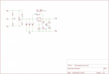
These boards are quite nice, they have TO220 diodes for rectification. the application is to turn 7-8VAC into 6.3VDC at about 1-2A.
Cooler :SK129-50
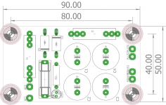
Main filter caps: 7.5mm pitch 16mm diameter electrolytics of 2200uF total capacitance per Ampere of output current minimum.
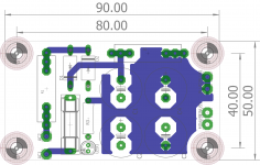
Dimensions: 49x100mm
Connectors : Faston 6.3mm
Mounting holes M4 on a 40x90mm square.
These boards are quite nice, they have TO220 diodes for rectification. the application is to turn 7-8VAC into 6.3VDC at about 1-2A.
Cooler :SK129-50
Main filter caps: 7.5mm pitch 16mm diameter electrolytics of 2200uF total capacitance per Ampere of output current minimum.
Dimensions: 49x100mm
Connectors : Faston 6.3mm
Mounting holes M4 on a 40x90mm square.
Attachments
-
LDO supply pcb ver2 panelized 100x100mm.zip287.5 KB · Views: 147
-
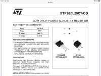 STPS20L25CT.jpg244.7 KB · Views: 338
 -
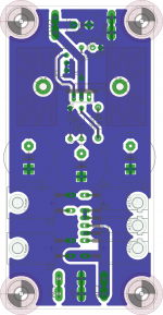 Print koper onder.png153.5 KB · Views: 260
 -
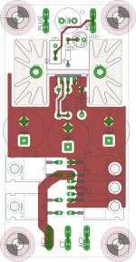 Print koper boven.png142.7 KB · Views: 263
 -
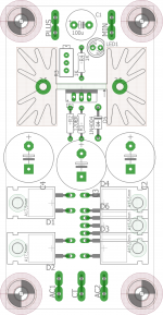 Print geen koper.png129 KB · Views: 302
 -
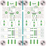 PCB panelized.png232.8 KB · Views: 392
 -
 Schema.jpg332.6 KB · Views: 589
Telegram invite link to tube audio groups
I have created a channel with links to different groups that are tube-audio related.
New Gerbers will be posted there because it allows me to remove and or update the ones with errors.
invite link is : Telegram: Join Group Chat
I have created a channel with links to different groups that are tube-audio related.
New Gerbers will be posted there because it allows me to remove and or update the ones with errors.
invite link is : Telegram: Join Group Chat
Not everyone is as fond of telegram as i am.
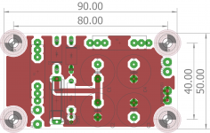
I made a board for a doubler, this board should be good for about 300-400V working voltage but YMMV. I did 1.5mm isolation between the top layer and components so that is the limiting factor.
I recently ran into a problem with the UniversalHV R1 and R2 boards. If you put the positive layers on top and the GND on the bottom.. You run the risk of shorts with some snap-in capacitors that have the can connected to the negative pin. Im gonna change some things on that board and call it version 3.
Its just a plain and simple board, not rocket science.
R1 is a trick i use sometimes to decrease the charging peaks in power supplies.
Sometimes its needed to use about 22-47R 5-7W here because this will make the capacitor charge over a wider part of the input sine wave. You can try this out for yourself in PSUD2: PSUD2
This resistor is also needed if you are trying to rectify from a toroidal transformer.. those have 1-5 Ohms of DC resistance... They can Blow a 8A bridge rectifier right in half if you put big caps directly behind the bridge..
Suggested diodes are standard UF5408. I dont beleive in Sillicon carbide diodes for 50Hz rectification.. Money better spend on a very nice output transformer.
The design package is something new, this is the complete package with gerbers and EAGLE board files if you want to change something..
You're welcome, the board was about 20 minutes of work and i hope it makes a lot of people happy.
Attachments
-
Gerbers capacitor multiplier GM70 thread fixed error.zip75.5 KB · Views: 133
-
Capacitor multiplier supply DIYAUDIO DESIGN PACKAGE.zip725.5 KB · Views: 124
-
 Bottom layer.png122.1 KB · Views: 271
 -
 Top no copper dimensions.png110.5 KB · Views: 212
 -
 Top layer fixed .png124.1 KB · Views: 329
 -
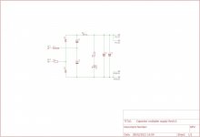 Schematic.jpg312.3 KB · Views: 342
Hiya v4lve lover 😀. Thank you for the great designs.
Would it be possible to modify the DHT regulator for higher current (e.g. 2.5A for the 2A3 valve)?
Would it be possible to modify the DHT regulator for higher current (e.g. 2.5A for the 2A3 valve)?
Yes that is entirely possible, first i will explain to you how you do it:
I should point out that the R0.0 boards have an error in them: D1 is reversed, if you check the datasheet for the 337 you will realize this protection diode is in reverse.. Happens to the best of folks i guess.
You only need to change the LM337 to LT1033, the circuit stays the same. You can use the same values. except that you have to change R1 and R2 to approximately 0.39R 2W metal film types.
However i would advice against building a new amplifier with the 2A3 because.. The 2A3 went obsolete when the 6A3 came out. And there is the 6B4G which is a 6A3 with an octal base (Much nicer and you can get cheap Beltons for 3USD instead of shelling out big for good UX4 sockets ) Russian NOS 6B4G can be found still on eBay at less than half of the new production 2A3. And they are one of the nicest sounding DHT's..
Furthermore if you use a regulator that need 4V headroom at 2.5A thats 10W off wasted energy. But if you only need 1A thats 4W. Furthermore you lose about 2V over the diodes and the CRC filter.. thats a difference of 2W VS 5W.
Further information can be found here: DHT heater supply design
If you use a wire bridge over D1 and D4 you can lower the dropout.. Just get rid of the 337/1033 altogether and use a bit more resistance in the RC filter..
The same goes for the clamping diode at the input of the current source, a BAT43 has about 350-400mV forward versus 650 mV for a run of the mill 1n4148. If you do both of these things.. you can get about 1.5V dropout. At the expense of slightly worse noise.. Estimate 200uV with prereg 500uV without.
You choose the combination of the clamping diode and the two current sense resistors so that the current source can output about 125-150% of nominal current. This is because using a pure current source may lead to damage of the filaments over time, because they heat up very slowly when you use a current source...
Last edited:
Thanks you for the info 🙂! Very useful!
I'm aware of the 6A3 and 6B4G, and I'll definitely try a build with them at some stage. However, I have a few pairs of 2A3 and one pair of 45 on hand that I'd like to use.
I'm aware of the 6A3 and 6B4G, and I'll definitely try a build with them at some stage. However, I have a few pairs of 2A3 and one pair of 45 on hand that I'd like to use.
Id sell those and get the Russian 6B4G. 2.5A is at the limit of what this regulator is capable off. this is due to the fact the opamp can only source about 10-15mA base current for the transistor. Looking at the 2SC6144 curves we get approx 3A with 10mA base current at 1V VCE. I have a regulator for 3-15A but its quite expensive to build due to the parts used...
Also there are gerbers in the group buy for the power supply board. i may or may have not posted them here as well.
I had some AD822 opamps to try instead of LM358 but i found that the slight decrease in noise was not worth $5 more per opamp
I had some AD822 opamps to try instead of LM358 but i found that the slight decrease in noise was not worth $5 more per opamp
Boards for current sources
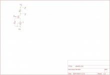
Upon request,
This is a simple board for a 10M45S or DN2540 or what have you CCS module.
At current you can get 5 panels for 2USD at JLCPCB, that works out at approx 60 PCB's so a little under 3 cents each once you break them in pieces.
I used the IRF840 mosfet footprint for convenience, as this is only a quick and dirty board.
Pot is a bourns 25 turn 3296 series pot. suggested value you'd have to look at the 10M45S datasheet.
Gate stopper on the depletion mode FET is not too critical 470R-1K
Attachments
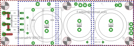
UniversalHV REV3
I reworked the UniversalHV boards, this is REV3.
I put the GND plane on top, and the positive planes on the bottom, so theres no chance of shorts between the aluminium can on the snap-In capacitors.
I reworked the UniversalHV boards, this is REV3.
I put the GND plane on top, and the positive planes on the bottom, so theres no chance of shorts between the aluminium can on the snap-In capacitors.
Attachments

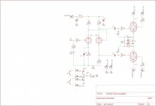
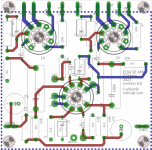
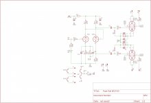
EL84PP board ECC82/12AU7 Phase splitter.
I re-rolled the 16GK6 boards a few pages back for the EL84.
I have some boards in the mail as of writing, 8 PCB's available for those who want to support the free gerbers drive. I can source everything you need for these boards.
Cheers,
V4LVE
I re-rolled the 16GK6 boards a few pages back for the EL84.
I have some boards in the mail as of writing, 8 PCB's available for those who want to support the free gerbers drive. I can source everything you need for these boards.
Cheers,
V4LVE
Attachments
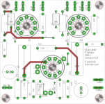
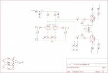
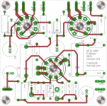
EL84 SE board.
I had some spare time on my hands yet again. So lets topkick once again.
Here is a board with identical dimensions, but i made it into a EL84 SE this time.
Two channels on one 100x100mm board.
You can use just about any double triode as driver.
For the russian 6N1-6N3 series it is possible to connect Pin9 to GND and use pin 4+5
You can get these boards plus all the parts from me. €20 flat for a parts kit.
Cheers,
V4lve.
Attachments
Great thread,
To many projects at moment, but great information and thanks for posting gerbers. Possible el84SE build in the future.
MM
To many projects at moment, but great information and thanks for posting gerbers. Possible el84SE build in the future.
MM

- Home
- Amplifiers
- Tubes / Valves
- V4lve lover's free Gerbers thread