This is going to be the topic where i post Gerber's that you can order yourself. Just don't sell the boards please, allthrough there is nothing i can do to stop you from doing so.
Suggested board house is JLCPCB, those are the cheapest.
Most of what i post here are boards for tube projects. I will try to add some description of what exactly it is.
The fastons i use are 61-1536-11/0031 OSTERRATH. TME.eu symbol: FS1536/NC
However i do not offer warranty on my designs, so order at your own risk.
furthermore all through i have a lot of spare time please i'm no tech support.
If you see something that suits your needs but isn't quite to your taste, pm and i will make changes for a small fee.
If you want to send me something for my efforts, my paypal is on some of the boards.
Last edited:
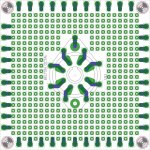
Octal experimenting PCB Belton Octal.
These are experimenting PCB's 80x80mm M3 holes.
Made for the belton octal sockets.
You need a m3 15mm spacer to mount the socket flush to the board.
Fastons are 61-1536-11/0031 OSTERRATH
These are experimenting PCB's 80x80mm M3 holes.
Made for the belton octal sockets.
You need a m3 15mm spacer to mount the socket flush to the board.
Fastons are 61-1536-11/0031 OSTERRATH
Attachments
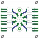
Belton octal experimenting PCB version two.
These are experimenting PCB's for the Belton 8 pin PCB mount sockets.
You need a m3 15mm spacer to mount the socket.
Holes are oversize so there is some getting used to using these.
For EU citizens: sockets are available here(no affiliation allthrough im a happy customer there): 8 polige buisvoet Belton PCB
Attachments
Don't forget the shout out for Naomi. (JLCPCB)Suggested board house is JLCPCB, those are the cheapest.
Attachments

Last edited:
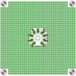
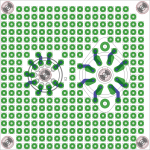
Noval experimenting PCB
I didn't quite get that reference, anyway.
These are Noval experimenting PCB's for the Chinese PCB mount sockets.
I get them here: 9 polige buisvoet pcb
However they are also on Ali express for a similar price.
Sorry for plugging that store so much, i hope its allowed.
I didn't quite get that reference, anyway.
These are Noval experimenting PCB's for the Chinese PCB mount sockets.
I get them here: 9 polige buisvoet pcb
However they are also on Ali express for a similar price.
Sorry for plugging that store so much, i hope its allowed.
Attachments
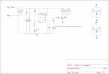
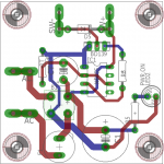
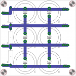
555 based time delay boards.
These are boards for time delays with 555 IC's. These will switch the relays on at a predetermined time after the AC is connected to J1 and J2
Two boards in a panel of 100x100mm.
Time is approx 1.1*R*C with R being the resistance between pin 2 and GND and C being the value of CT.
List of relays:
Cheap 6VDC
HF115F/006-1Z3B HONGFA RELAY tme.eu
expensive:
Finder 44 series.
Cheers!
Attachments
Last edited:
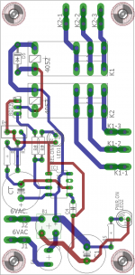
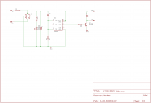
Yet another 555 delay for use with octal relays
These are small boards for use with octal relays.
See my previous post for circuit description, you might need to tweak the BD139 base resistor if your coil uses corpus amounts of current.
Apart from that its a straightforward circuit.
size is a little under 2x2'' with m3 mounting holes.
These are small boards for use with octal relays.
See my previous post for circuit description, you might need to tweak the BD139 base resistor if your coil uses corpus amounts of current.
Apart from that its a straightforward circuit.
size is a little under 2x2'' with m3 mounting holes.
Attachments
No substitute for capacitance.
These are 100x180mm boards for carrying lethal amounts of Jules, usable up to about 450V
Mounting holes again are m3, electrolytic size is 35mm snap in. And the footprint for the two film caps is C375-192X418. in layman's terms 37.5mm and 19.2 by 41.8mm
I have two of these boards spare in swap meet if you want these ASAP.
Attachments
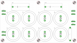
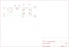
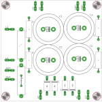
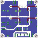
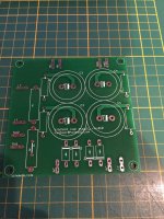
Stacked capacitor supply
This is a 100x100mm board for a stacked capacitor supply.
My idea was to use a high value resistor, EG 47K 7W for R6 and connect a delay board at SW1, SW2.
You can either use on board RC filtering, or connect an external choke. Usable up to about 600VDC but YMMV.
These go well together with :
eBay item number:
184091859118
Suggested diodes are BY2000.
Attachments
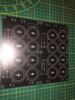
High voltage capacitor boards.
100x100mm m3. 30mm snap-in's.
Usable for higher voltages, but please use plastic standoffs to limit the possibility of arc-over.
suggested stand-off is a 20mm long polystyrene standoff with an internal M3 thread.
These voltages are LETHAL, i suggest you know what you are doing, keep one hand in pocket at all time!.
Attachments
Last edited:
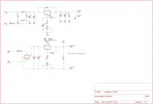
Nixie +180V and +5V regulator boards
These are buck and boost boards for furnishing +180V 20mA and +5V 500mA.
MC34063 based, nothing beats the classics.
The transistor is not marked in the schematic, but that's a BC557 or equivalent, not too critical. BC327 is slightly better i think.
If you put a 330R resistor in the position of D1 you can use a switching transistor instead of a FET. BUT11 for example.
I have not (yet) tested these boards, but the schematic is so straightforward it ought to work.
size is 50x100mm, not panellised this time.
Attachments

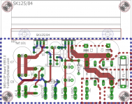
Heaters plus negative SK125 heatsink
This is a board for two supplies to furnish both DC heaters for preamp tubes and the bias needed in an amplifier.
EDIT THERE IS A MISTAKE IN THE BOARD, C5 cannot be used without putting a diode over R1.
Suggested for the positive low voltage supply : LD1085 (Do not forget to put a 100uF electrolytic on the output as this is required for stability) also do not forget the reverse protection diodes.
Heatsink is a SK125-84. SK125-84SA FISCHER ELEKTRONIK - Heatsink: extruded | TO220; black; L: 84mm; W: 30mm; H: 28mm; 6K/W | TME - Electronic components
Fuse holder is a ZHL15 PTF/15 Stelvio Kontek - Fuse holder | cylindrical fuses; Mounting: THT; 5x20mm; -30/85degC; ZHL15 | TME - Electronic components
Diodes for the low voltage: SB540 or MBR340 or equivalent low forward diodes.
Suggested for the negative bias supply: TL783 (This one is stable with no cap on the ouput, don't use a cap on the output if you input more than 75VAC). Also remember that this ic WILL NOT REGULATE BELOW 15mA output current, so please make sure that your biasing network pulls at least 10mA.
Remember that the heater voltage regulator needs 8VAC in to provide 6.3VDC.
I suggest this toroid: TST 20/001 INDEL - Transformer: toroidal | 20VA; 230VAC; 8V; 2.5A; 0.4kg; Leads: cables; TST20W/8V | TME - Electronic components
Attachments
Last edited:
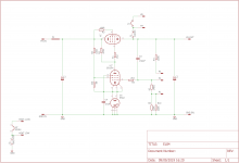
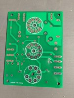
Tube power supply EL84 EF80/184 85A2
This is a very straightforward board for a power supply with EL84/EL86/PL84.
Classic tube topology, suggested reference tube is a 85A2 56. Control tube can be EF80 or EF184. And anything pin compatible with the EL84 will do for a pass tube.
Use up those PL84 this way.
You can use a PL84 and put the heater in series with the EF184, the isolation is good for 250V on these kind of tubes. you then need about 21V for the tubes combined, you can float that at +100V from a divider from the output, and furnish it from a 24VAC transformer with a 22R series resistor. (3W or more)
Size: 75x100mm M3 mounting holes, the centres of the tubes have a M3 hole in the middle so the PCB can function as a drill guide.
The sockets are mirrored, these are designed for under chassis mounting.
Attachments
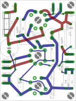
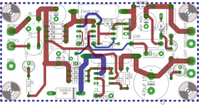
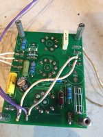
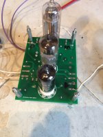
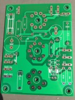
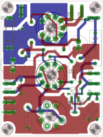
The same but different. 6C19P this time
This is a board along the same lines as the previous example, but the pass tube is a 6C19P.
Note that ive used a plane for the anode connections(The 6S19P has multiple anode connections intended to increase cooling of the anode)
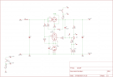
This board has been built by multiple people and works flawlessly. P1 P2 and P3 are connections for an external potentiometer. Suggested value: 100K 3W wire-wound. You are free to use the on board trimmer, but a 100K 3W wire-wound pot has a way lower tempco.
If you need to calculate the resistors to set the output voltage: remember that G1 of the EF80/184 is at approx 83V with respects to ground. So you calculate the voltage divider for two conditions, one with the pot added to the bottom resistors and one with the pot added to the top resistors. From that you can approximate the adjustment range.
J1 needs to be put in place, otherwise the heater of the 6C19P will float with respects to the cathode/Vout.
J2 is optional, and serves to ground the heater of the EF80/184 at this exact point.
This is a board along the same lines as the previous example, but the pass tube is a 6C19P.
Note that ive used a plane for the anode connections(The 6S19P has multiple anode connections intended to increase cooling of the anode)
This board has been built by multiple people and works flawlessly. P1 P2 and P3 are connections for an external potentiometer. Suggested value: 100K 3W wire-wound. You are free to use the on board trimmer, but a 100K 3W wire-wound pot has a way lower tempco.
If you need to calculate the resistors to set the output voltage: remember that G1 of the EF80/184 is at approx 83V with respects to ground. So you calculate the voltage divider for two conditions, one with the pot added to the bottom resistors and one with the pot added to the top resistors. From that you can approximate the adjustment range.
J1 needs to be put in place, otherwise the heater of the 6C19P will float with respects to the cathode/Vout.
J2 is optional, and serves to ground the heater of the EF80/184 at this exact point.
Attachments
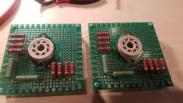
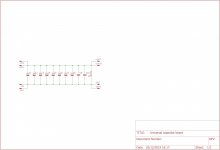
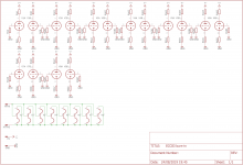
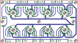
ECC8X burn in board.
This is a board for burning in ECC8X tubes. There are grid cathode and anode resistors to simulate real world operating conditions. Please see their respective datasheets for guidelines.
Really useful if you need to burn in a bunch of ECC tubes
Board measures 180x100mm m3 mounting holes.
These sockets i know will fit for sure : 9 polige buisvoet pcb
Attachments
Last edited:
thanks a lot v4lve lover, this is a great service to diy'ers around the world....i also use the JLPCB and can't really complain....they are super fast and cheap...
we are running build outs/teach ins in Manila, but the pandemic stopped us from doing any of those this 2020....perhaps 2021 is a better year...
btw, may i suggest a board for testing the sections of dual triodes, ala srpp?
reason being, to be able to select very good matched tubes at the desired operating voltage and current...
Last edited:
Thanks for the support,
People can also plug their ideas for PCB's here, if there is enough interest we'l do a group buy of 10PCB..
People can also plug their ideas for PCB's here, if there is enough interest we'l do a group buy of 10PCB..
You may certainly, what kind of sockets do you want on it? I think a combination of octal and noval right?
PM me, and we''l discuss details.
PM me, and we''l discuss details.
thanks, 9 pin miniatures and octals....some sort of a screening bed for tubes that will find its way to a finally built amp...
- Home
- Amplifiers
- Tubes / Valves
- V4lve lover's free Gerbers thread