Finally I assembled two channels and I am trimming the first one. I have the configuration with All FET NGF, single power supply. Here are my questions:
1) What voltage should I use ? Can I go straight to 24 V ?
2) How close to zero R11 should be +- 5mV is enough or should I be more obsessive ?
I did not solder the output devices yet. Some porn later on.
Thanks,
Davide
1) What voltage should I use ? Can I go straight to 24 V ?
2) How close to zero R11 should be +- 5mV is enough or should I be more obsessive ?
I did not solder the output devices yet. Some porn later on.
Thanks,
Davide

I used +/-24V with current limit during test.
But it will work well enough still at say +/-15V to allow you to check things as a first start.
Eventually you need to run it at operating voltage to trim DC offsets, etc.
For trimming R11, I would aim at < +/-10mV minimum, 5mV preferred.
After that you need to trim the power devices using the two biasing resistors.
Patrick
Any particular recommendation for a power supply? I would like to use 24V , but I think I could replace the on board resistors with regulated stage.
D
D
So,
First channel is running. I still have to adjust the output devices. The offset set around 5mV without correction with a 190mA bias. The Jfet are 10 mA. One thing I noticed is that it took quite some time to settle. It started at +130mV, then went to -40mV and, in 40 minutes, went down to 5mV. Did other builders observed this ? The heatsink temperature settled at 34C. It was a bit cold in the room.
Regards,
Davide
I don't have so much offset at the start.
But then I have only about 140mA bias.
So probably you need better coupling to the heatsink (I use Kerafol).
But a SHPP will protect your headphone against the 130mV.
Anything below 50mV is no issue IMHO.
I assume you use over-the-ear phones.
Patrick
But then I have only about 140mA bias.
So probably you need better coupling to the heatsink (I use Kerafol).
But a SHPP will protect your headphone against the 130mV.
Anything below 50mV is no issue IMHO.
I assume you use over-the-ear phones.
Patrick
There is something wrong: as soon as I disconnect the ground from the input, I get 20v on R11 and on the output.
D
D
Patrick just looking through the BOM's, in order to save a few pennies, can the following resistor values be substituted without much harm or compensation, I will likely choose BJT current mirrors as I have a few ZTX already stashed-
R12ab 910R for 1K
R23,24 220R for 240R
I have 1K and 240R MELF's on hand. No problem getting 220R in 1206 but 910R is hard to find in SMD unless I pay 12Euro shipping from Buerklin.
Anyone want some parts from Buerklin?
R12ab 910R for 1K
R23,24 220R for 240R
I have 1K and 240R MELF's on hand. No problem getting 220R in 1206 but 910R is hard to find in SMD unless I pay 12Euro shipping from Buerklin.
Anyone want some parts from Buerklin?
Changing R12a,b will change the overall gain.
You may (not must) compensate for this by changing R11 in proportion.
R23,24 is just gate stopper. 10% change has little effect.
You should learn to use LT Spice and find out for yourself using the .asc files in post#1.
Patrick
You may (not must) compensate for this by changing R11 in proportion.
R23,24 is just gate stopper. 10% change has little effect.
You should learn to use LT Spice and find out for yourself using the .asc files in post#1.
Patrick
Hi Patrick,
I just started with headphones.
Until now I was busy with my refspeakers v2 and I am still building some amplifiers for them.
But for late night listening or on holiday a headphone is more practical 🙂
So I just bought a planar headphone: the Verum 1
It's 12 ohm and 96db
I tried to adapt your ltspice circuits of the UTHAiM for a low impedance headphone: more current and lower gain.
Thanks for those circuits !
I modified the NFB and ZGFB circuits by:
- changed rail voltage from 24v to 18v and R21, R22 to 100 ohm to adjust the bias
- reduced the gain by changing R12, R11 and Rfb
0.5vin gives 1.5vout
I've put those modified circuits in the attachments
The FFTs in ltspice look good even for the ZGFB.
So I ordered some UTHAiM PCBs.
But just now I found out that you've designed a current drive headphone amplifier that is a perfect match
for planars that have an impedance curve that looks like a resistor.
I've read your pdf about current drive in which you write that the UTHAiM can be converted to a current drive circuit by changing hfe ratio of the current mirror.
Can you give me some advice how to convert the UTHAiM to current drive, is it just copying the current drive mirror circuit ?
Or do I better start from the new current drive circuit and new PCBs ?
Regards,
Danny
Attachments
Essentially you can copy the current mirrors of the SL Transconductance.
BUT that means you should use BJTs for the current mirrors.
And the transconductance gain should be adjusted to suit your particular load impedance.
Details can be found in that thread.
And you have enough information from both threads to simulate in Spice first.
You will need to design new PCBs.
Patrick
OK thanks,
Designing new PCBs is not (yet) something I 'm used to.
I'll stick to this UTHAiM ZGFB, Morde had great success with this circuit.
In the zero global FB version the gain can be adjusted with R12 and R11.
Is there an optimal ratio between R12 and R11 when I change them for lowering the gain ?
Designing new PCBs is not (yet) something I 'm used to.
I'll stick to this UTHAiM ZGFB, Morde had great success with this circuit.
In the zero global FB version the gain can be adjusted with R12 and R11.
Is there an optimal ratio between R12 and R11 when I change them for lowering the gain ?
I played a little more with the UTHAiM ZGFB in ltspice and I like it 🙂
It's very flexible, I can even adjust the ratio between H2 and H3.
Here's what I did:
- changed the laterals to Exicons, thanks to the models from Ian Hegglun
- changed rail voltage from 24v to 18v and R21/R22 to 100/150 ohm to adjust the bias and compensate the difference between N and P.
- reduced the gain by changing R12, R11 (0.5vin gives 1.5vout)
- reduced R11 to 1.5K, by changing R11 the ratio H2 and H3 changes, it's like taking some H3 and converting it to H2 🙂
- adjust R6 or R8 to set the DC output to 0v, R6 and R8 (bias) are also less sensitive with a lower R11
- removed R31 for lower output impedance
Is it OK to remove R31 ?
Regards,
Danny
Attachments
Last edited:
R31 is there to allow you to change the current ratio between P & N MOSFET.
Already described somewhere in this thread.
And yes, you can skip.
Patrick
Already described somewhere in this thread.
And yes, you can skip.
Patrick
OK thanks,R31 is there to allow you to change the current ratio between P & N MOSFET
I've changed the current ratio P & N by changing R21/R22 from 100/100 to 100/150 ohm
No reason anymore to keep R31
I might be late to the party here.
In fact I have ordered some SLHPA from Patrick just before the lockdown. Unfortunately most of my components for the SLHPA are at my work. I do not know when I will be able to get there so I took over UTHAiM from passive420. He was kind enough to sent the boards and the parts to my home address (not to the office!).
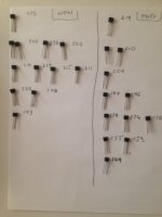
I have measured today the BJTs for the current mirrors.
I would appreciate if somebody could look at the numbers and advise whether I need a bigger pool. My understanding is that I could get away with less precisely matched pairs in a quad in the cascode positions.
But please let me know if you think the values are all over the place...
PS I have done pairs matching before, getting quads seems to be more difficult...
In fact I have ordered some SLHPA from Patrick just before the lockdown. Unfortunately most of my components for the SLHPA are at my work. I do not know when I will be able to get there so I took over UTHAiM from passive420. He was kind enough to sent the boards and the parts to my home address (not to the office!).
I have measured today the BJTs for the current mirrors.
I would appreciate if somebody could look at the numbers and advise whether I need a bigger pool. My understanding is that I could get away with less precisely matched pairs in a quad in the cascode positions.
But please let me know if you think the values are all over the place...
PS I have done pairs matching before, getting quads seems to be more difficult...
Attachments
- Home
- Amplifiers
- Headphone Systems
- UTHAiM -- Just for Fun