New USSA-5.2 version info
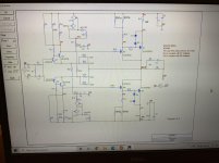
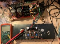
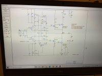
This is the schematics of the v5.2 and one channel under test. Main change is the driver transistors and adjustment of resistors value accordingly.
Fab
This is the schematics of the v5.2 and one channel under test. Main change is the driver transistors and adjustment of resistors value accordingly.
Fab
Attachments
New version 5.2 THD
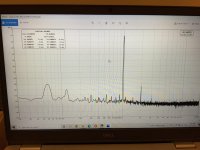
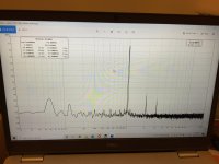
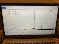
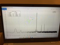
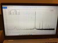
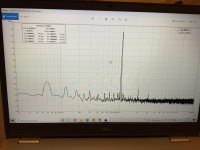
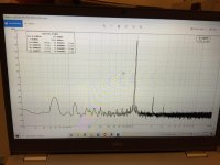
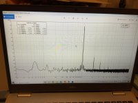
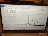
Here is the THD measurements profiles done at 1KHz under 8 ohms load for different powers :
Fab
Here is the THD measurements profiles done at 1KHz under 8 ohms load for different powers :
Fab
Attachments
-
 DBCFC04F-C9CF-43B9-BBF4-7D9662D3B219.jpg950.9 KB · Views: 418
 -
 91DA5900-9310-4D07-9649-1FAB0951362E.jpg759.6 KB · Views: 395
 -
 01CD0CC3-94E5-445C-8E50-0DAD5D158F18.jpg776.1 KB · Views: 376
 -
 82A9D920-0A92-468E-B687-CC62B78F7D05.jpg731.7 KB · Views: 119
 -
 6B7FEF19-63E6-46CB-A356-761F40B088DD.jpg745.4 KB · Views: 136
Hi Vunce
Thanks for your appreciation")
I know that many USSA5 pcbs sold have not been assembled yet and maybe the components were not secured in time. So I want to let the chance for these peoples to build the amp with no problem in sourcing components. And also for future builders
From the thd profile, negative phase H2 is king
Only H2 and H3 visible up to at least > 4W rms.
Fab
Thanks for your appreciation
I know that many USSA5 pcbs sold have not been assembled yet and maybe the components were not secured in time. So I want to let the chance for these peoples to build the amp with no problem in sourcing components. And also for future builders
From the thd profile, negative phase H2 is king
Only H2 and H3 visible up to at least > 4W rms.
Fab
Last edited:
Hi manniraj
Yes that’s true that 1W is usually enough. But in my case I have 87dB efficiency 4 ohms speakers and I usually listen at moderate level. Anyway as you can see even at 4W there is no presence of bad distortion. Even at higher power the amplitude profile is decreasing while harmonics becomes higher.
yes indeed a very accessible amplifier .
Fab
New USSA-3.2B version
Still in the process to update the USSA amp series with readily available drivers, after the USSA-5, my next candidate was the USSA-3B so it has become the USSA3.2B. The « .2 » means vertical mosfet FQP3 complementary drivers. “B” stands for bjt power output.
This is the same topology as the USSA-3.0 or 3.1 or 3B, except:
1) Drivers are FQP3. Recommended from the PASS forum over the IRF ones that I personally dislike;
2) LSK/LSJ (or 2SK/2SJ) jfet IDSS is now much higher [6- 12]ma “B “ grade which is the only grade easily available at this time in new stock;
3) DF is higher;
4) THD is overall the lowest one obtained from all USSA-3 series (if that matters).
THD profile taken at some RMS power for 1KHz into 8 ohms. THD profile is again tuned with a potentiometer P3.
My first build is using MJL bjt output.
Fab
Attachments
-
 456B5CF1-7319-4EEF-8CD8-AB4D03CB6AA9.jpg885.1 KB · Views: 249
 -
 BE1717D5-FF50-4277-9A78-151EA00B5D2C.jpg977.5 KB · Views: 211
 -
 A918F99A-8686-47DC-8EAB-811C53212D29.jpg762.2 KB · Views: 110
 -
 F899EF8C-F822-427A-BF2C-3BF1669DF8A1.jpg784.8 KB · Views: 104
 -
 7B6BC899-2380-4135-A76E-32EC675EF09C.jpg777.6 KB · Views: 166
Last edited:

I have already built this one. This is not the same sonority at all. It's like bananas and oranges
Fab
Fab - you able to provide more comparison on the Rod Elliot P101 you build vs USSA and some other amps? Would be interesting. Thanks.
Hi stretchneck
This is a difficult question and remind that it is only my personal and subjective opinion… only cited a few of amps I have done in the past. This is only very summarized, incomplete and not to be taken in absolute terms.
The P101 is typical class AB amp also with lateral outputs. I must admit it has been a while (several years since I listened to this amp, now disassembled). I remember it could sound correct but not a keeper for me and my friends who are diyers.
The Goldmund Telos clone which is also a class AB lateral mosfet amp was more fun to listen too (more sweet) and for my friends too.
The NX amp is a bjt output and quite different sound and very dynamic (its biggest strength I would say). I wanted to do a lateral mosfet output with same topology but finally ended up on a different path with the USSA amps series. However USSA shares the same symmetrical CFA type of topology.
I also built SKA, Pass F5 and Hiraga super class A. I will not do a complete comparison for these.
When I listen to any of the class A USSA3 or USSA5 amp versions they appear to sound bigger (to me) than these class AB amps listed above. However I must admit that the NX had a deep soundstage.
As for for the class A ones listed above, the USSA amps present not only a big soundstage but very well defined instruments spatially localized with beginning and end of notes clearly shown.
But I may also be biased …
Fab
Last edited:
Hi Alan,
Someone is selling two fully assembled PCBs of USSA5 here
https://www.diyaudio.com/community/threads/pair-of-fully-populated-ussa-5-25w-class-a-board.377760/
Do
Someone is selling two fully assembled PCBs of USSA5 here
https://www.diyaudio.com/community/threads/pair-of-fully-populated-ussa-5-25w-class-a-board.377760/
Do
hi baggerbole
The jfet need to have IDSS matched within 8%. Driver mosfet should be matched < 100mv for VGS at (20 to 40)ma ID. Output dual die mosfet only needs to be selected (-S suffix) with same VGS Color code between N & N, and P & P to have similar characteristics between left and right audio channels.
note:
I am almost out of USSA pcb so I was not sure how many pcb I wanted to keep for further development - if required. Afterthought I have one pair available. I had some previous request so please put your name down here if you are committed to buy this pair. In case I have enoigh request I may decide to run another small batch….
Fab
- Home
- Group Buys
- USSA-5 PCB GB