Fab thanks for attention.
i found the 1.3p version. i was looking an earlier version 0.6......
BR
Vasilis
i found the 1.3p version. i was looking an earlier version 0.6......
BR
Vasilis
Hi X,
I pick them up from eBay, I believed they were reclaimed heatsinks from solar power inverters. It’s deceiving in the pictures, it does look like a cube but if you looked at the footprint from the top it’s definitely wider than deep. (17” x 12.5”)
Correct re inverters!! My solar inverter broke down and had to be replaced; The contractor gave me a present of two broken inverters with identical heatsinks! Now to salvage them!
Good score Brianco!!
These HS are awesome for Class A cooling, I could leave my USSA5 powered on 24hrs straight. With 21°C ambient temperature the sinks don’t go higher than 47°C.
These HS are awesome for Class A cooling, I could leave my USSA5 powered on 24hrs straight. With 21°C ambient temperature the sinks don’t go higher than 47°C.
Hi Bfpca
Any update on your build ?
Fab
Yes, I have been busy but have made some progress on the chassis. Keep in mind that the chassis, power supply and heatsinks are made from my parts bins. I have an extra set of boards and if I like this amp I will be building a more conventional one in the future. I had to build a DC protection/power on delay board first. Since getting expensive factory built speakers I don’t like running DIY solid state gear without protection relays. I got to the point where I mounted the amplifier modules in the chassis last night. I fired it up and the 2 channels settled in at about 43c temperature and offset was .5mv and 1.4mv. This is impressive stability considering that I adjusted them on the bench using a pair of lab power supplies. My PS voltages ended up at +-27v
I am using a 34v 800w transformer that buzzes like crazy if you load it more than 200w continuous. The manufacturer replaced it with a new one which buzzes only slightly less and he gave me the old one. I use a transformer with a low voltage secondary winding to adjust the line voltage down to 104v so I get the correct voltage out of the toroid(31v) for a LC filtered supply. 25mh .35 ohm chokes and about 50kuf of capacitance on each half the supply. The big chokes, rectifier and the transformer are located on the front bottom portion of the chassis. The caps, voltage adjust transformer terminal strip and DC protection/delayed on board are mounted on a raised platform above the transformer.
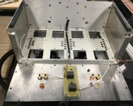
The heatsinks are overkill. With a small amount of air flow and bias around 1 amp the output fets are barely hot. Lots of room for a bit more bias current or voltage. I still need to finish the input wiring. I was wanting to ask you what you normally do to connect chassis ground to the audio or power supply ground? The exterior of the chassis is not finished. Once I get the input/ground finished I will let it cook for a while, re adjust bias and offset and then have a listen. For some reason I can only upload 1 picture. I will see if I can add more after posting
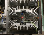
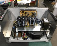
OK first picture is rear of chassis before amp modules installed with back panel/ relay board being wired, second picture is looking down on one of the channel modules after install. Third picture is the front half of the chassis showing the upper and lower levels. The big brown and black thing is the transformer and you can just see the chokes under the left side of the upper level platform.
Attachments
Last edited:
Hi Bfpca
You have made good progress.
You have an impressive build from your parts bins😛
I notice that you use a small Wima cap for input of amp. The BOM suggests better parts for that important cap. You may consider doing an upgrade to get best sonic.😉
The chassis ground is connected to the mains inlet earth ground. To connect chassis ground to Power Supply ground you can use a ground breaker circuit or an anti-parallel medium power diodes arrangement in parallel with a small value resistor.
To reduce noise at input I often install a 47-100nF cap value between RCA socket ground and chassis.
Do not forget to perform about 40 hours or more of breakin before concluding on the sound. 😉
Looking forward to seeing your next report.
Fab
Love looking at your built!Yes, I have been busy but have made some progress on the chassis. Keep in mind that the chassis, power supply and heatsinks are made from my parts bins. I have an extra set of boards and if I like this amp I will be building a more conventional one in the future. I had to build a DC protection/power on delay board first. Since getting expensive factory built speakers I don’t like running DIY solid state gear without protection relays. I got to the point where I mounted the amplifier modules in the chassis last night. I fired it up and the 2 channels settled in at about 43c temperature and offset was .5mv and 1.4mv. This is impressive stability considering that I adjusted them on the bench using a pair of lab power supplies. My PS voltages ended up at +-27v
I am using a 34v 800w transformer that buzzes like crazy if you load it more than 200w continuous. The manufacturer replaced it with a new one which buzzes only slightly less and he gave me the old one. I use a transformer with a low voltage secondary winding to adjust the line voltage down to 104v so I get the correct voltage out of the toroid(31v) for a LC filtered supply. 25mh .35 ohm chokes and about 50kuf of capacitance on each half the supply. The big chokes, rectifier and the transformer are located on the front bottom portion of the chassis. The caps, voltage adjust transformer terminal strip and DC protection/delayed on board are mounted on a raised platform above the transformer.
The heatsinks are overkill. With a small amount of air flow and bias around 1 amp the output fets are barely hot. Lots of room for a bit more bias current or voltage. I still need to finish the input wiring. I was wanting to ask you what you normally do to connect chassis ground to the audio or power supply ground? The exterior of the chassis is not finished. Once I get the input/ground finished I will let it cook for a while, re adjust bias and offset and then have a listen. For some reason I can only upload 1 picture. I will see if I can add more after posting
OK first picture is rear of chassis before amp modules installed with back panel/ relay board being wired, second picture is looking down on one of the channel modules after install. Third picture is the front half of the chassis showing the upper and lower levels. The big brown and black thing is the transformer and you can just see the chokes under the left side of the upper level platform.
Hi Fab
I have started my USSA-5 amp build with the first amp board which was set earlier with combining multiple resistors for RV1A to get 27R. Now I got the Dale single resistor of 27R and changed and started setting the steps and below are the results:
Did the 8.17.1 again with P1/P2 to adjust the bias to 50mV and below are the values:
VGSP = 1540, VGSN = 979 which makes it like
R13=47R, RV2B = 47R, RV1B = removed
RV1A = 27R
RV2A = Jumper
So im3pre = 1540 / (47+27) = 20.81mA
R14=47R
RV2A = 0 (jumper)
So im4pre = 979 / (47+0) = 20.82mA
DC Offset = 1mV
The above VGSN/VGSP values are when the bias was at 50mV. I have not calculated the VGSN/VGSP after setting the bias to 61mV.
If you remember my target bias was 65mV (1.3A), hence the calculations. But now I see that the heat sink is too hot after 30-35mins with 61mV. So based on the above calculations and my bias/current should I leave it as is it or do I need to change something and maybe target for 50mV? Can you please suggest what changes should I do or can I live with 60-61mV bias with the above values of RV1A being 27R?
Thanks
Last edited:
Hi manniraj
Based on the expected transconductance of the output mosfet I have estimated an average of 2.
So an increase of 300ma (50mv to 65mv) of bias gives roughly in increase of about 150 mv on VGS (300ma/150mv).
Thus 979mv + 150mv = 1130mv
1130mv / 47 ohms = 24mA drive current which is about the low limit used so far for the USSA5 ( version 0 original with mosfet drivers).
Now if you go lower output bias than 65mv then you may have to increase the mosfet driver current.
So you can target >= 23ma at your selected output bias current thus reduce resistors value accordingly in order to get the same driver polarisation as the other USSA5.0 units built so far. Higher driver current provides marginally better linearity for the drivers. However, I have not experienced the difference , if any, in sound with 21 or 22ma bias. In the end it may not make a real noticeable difference but I just wanted to let you know about more optimal driver current value...
One thing for sure I would not wait to change the resistors value to continue your progress...
If you want to increase the driver current you can simply change both R13 and R14 from 47 to 43 ohms if you already have them.
Fab
However ha
Last edited:
Thanks Fab, with heat sinks having some air flow at the bottom and placing it fins vertical I was able to dial the bias to 65mV and ran it for more than 30mins. Not too hot and I think the heat sinks were able to handle the heat.
Now at this bias the
VGSP=1773 so bias current 1773/74 = 23.95mA
VGSN=1189 so bias current 1189/47 = 25.29mA
There is a difference at the positive side not having enough target current of 25mA. All the other values being same with offset at <1mV.
Now at this bias the
VGSP=1773 so bias current 1773/74 = 23.95mA
VGSN=1189 so bias current 1189/47 = 25.29mA
There is a difference at the positive side not having enough target current of 25mA. All the other values being same with offset at <1mV.
My second amp board also is up and running with all set and following values:
VGSP = 1785, VGSN = 1215 which makes it like
R13=47R, RV2B = 47R, RV1B = removed
RV1A = 25R (calculated this with 50mV bias)
RV2A = Jumper
So im3pre = 1785 / (47+25) = 24.79mA
R14=47R
RV2A = 0 (jumper)
So im4pre = 1215 / (47+0) = 25.85mA
DC Offset = 1.3mV
With the bias at 65mV the above VGSP and VGSN values.
Thanks Fab, with heat sinks having some air flow at the bottom and placing it fins vertical I was able to dial the bias to 65mV and ran it for more than 30mins. Not too hot and I think the heat sinks were able to handle the heat.
Now at this bias the
VGSP=1773 so bias current 1773/74 = 23.95mA
VGSN=1189 so bias current 1189/47 = 25.29mA
There is a difference at the positive side not having enough target current of 25mA. All the other values being same with offset at <1mV.
This is excellent results, 24mA is quite alright. Only 5% difference between positive and negative sides is within 12% target of the Manual thus no issue here. 🙂
With your second sets of results We can now calculate the real transconductance of your specific mosfet and it is more than 2... 😉
You should let the amp for more than 2 hours as a burnin process and Temperature stability verification.
Since the lateral mosfet has positive temperature coefficient at high bias you do not have to worry about thermal runaway 😉
Fab
Last edited:
This is perfect too.🙂My second amp board also is up and running with all set and following values:
VGSP = 1785, VGSN = 1215 which makes it like
R13=47R, RV2B = 47R, RV1B = removed
RV1A = 25R (calculated this with 50mV bias)
RV2A = Jumper
So im3pre = 1785 / (47+25) = 24.79mA
R14=47R
RV2A = 0 (jumper)
So im4pre = 1215 / (47+0) = 25.85mA
DC Offset = 1.3mV
With the bias at 65mV the above VGSP and VGSN values.
Fab
Thanks Fab, I have made the dual mono PSU boards and will run each board with a separate transformer and PSU for 2 hrs and see the temp as well as the bias/offset. Now need to make mono bloc cabinet and planning to connect to my Audio Nirvana super 8+. I am planning to start building my Troels Gravesen TQWT MKII kit next month, so hopefully this amp justifies its high sensitivity 🙂
thanks again, and I will try to hear the amp tomorrow on my test speakers first.
thanks again, and I will try to hear the amp tomorrow on my test speakers first.
Hi manniraj
Seems like a plan.
If you use hi efficiency speakers you don’t even need as much 25Wrms into 8 ohms ( I use my USSA5.1 to drive my Troels SBA-10 speakers at 87dB efficiency😉 ).
But the day you change speakers then your amp will be more suitable at 25Wrms 🙂
Fab
Seems like a plan.
If you use hi efficiency speakers you don’t even need as much 25Wrms into 8 ohms ( I use my USSA5.1 to drive my Troels SBA-10 speakers at 87dB efficiency😉 ).
But the day you change speakers then your amp will be more suitable at 25Wrms 🙂
Fab
Last edited:
The amplifier is alive and playing beautifully in my make shift huge cabinet. I have now run it for around 2 hrs. Dead silent and I have used a big NTC thermistor as a soft start on the AC mains and no thump at all. With my Audio Nirvana super 8" drivers rated at 96db the amp is 99% dead silent and I can hear a very very slight hiss when I keep my ear close to the drivers. Otherwise I haven't build an amplifier which was so silent and that too with dual mono design. PSU's are borrowed from a friend temporarily which I built using the Prasi's CRC with LT4320 regulators.
Bias is stable 65mV with offset being <1mV even after 1 hr of playback.
How many hours should I run before making a judgement 🙂


Bias is stable 65mV with offset being <1mV even after 1 hr of playback.
How many hours should I run before making a judgement 🙂
Last edited:
Hi superb build manniraj!
Give it 30 to 50 hours burn in but right from the start these Fab’s designs are just amazing!
Enjoy it!
Do
Give it 30 to 50 hours burn in but right from the start these Fab’s designs are just amazing!
Enjoy it!
Do

- Home
- Amplifiers
- Solid State
- USSA-5 Build with Review