Thank you Fab!
That is a great start for me.
Can I send you a PM (e-mail) and with that the actual schematics to avoid any misunderstanding.
Please just answer when you have some time.
I do now want to post your circuit neither here not in a new thread, respect to your work unless you I can do it.
I have two transformer for this amp, one 800VA 28-0-28VAC, The other 1KVA 30-0-30VAC.
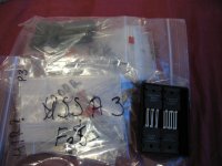
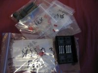
I purchased all the boutique parts (resistors, caps) plus the 2x2pair matched Exicon Fets, for drivers I have original Toshiba 2SK2013 & 2SJ213 .
It would be a big waste not to test it, or not build it. 😱😱
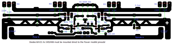
The last picture is my (art work) layout, will need to be modified to have the mentioned front JFets cascoded.
I work with Paint on the computer to draw my layouts ....
Also have the amplifier case (heatsink), a lot of stuff packed on the top at the moment and waiting for the PCB..
Thank you one more times!
That is a great start for me.
Can I send you a PM (e-mail) and with that the actual schematics to avoid any misunderstanding.
Please just answer when you have some time.
I do now want to post your circuit neither here not in a new thread, respect to your work unless you I can do it.
I have two transformer for this amp, one 800VA 28-0-28VAC, The other 1KVA 30-0-30VAC.
I purchased all the boutique parts (resistors, caps) plus the 2x2pair matched Exicon Fets, for drivers I have original Toshiba 2SK2013 & 2SJ213 .
It would be a big waste not to test it, or not build it. 😱😱
The last picture is my (art work) layout, will need to be modified to have the mentioned front JFets cascoded.
I work with Paint on the computer to draw my layouts ....
Also have the amplifier case (heatsink), a lot of stuff packed on the top at the moment and waiting for the PCB..
Thank you one more times!
Attachments

This would be an USSA3 twin Turbo version and from the many versions I have already done unfortunately it is not one of them…🙄
As Indicated privately to Gaborbela, when I release a design for use it is not only on paper and simulations but fully tested in practice for stability and optimized sound. This is a lot of work and - maybe selfishly- I favour my own projects and even that I am lagging behind…🙄
if one day it is on my list I will advise accordingly.
In the mean time, as an alternative to maybe consider the FSSA that uses cascaded jfet input stage and lateral mosfet as output…..
Fab
I understand it, FAB
I just wrote (answered) in private before I got this message.
I only (mostly) interested in a Class A amps!
Because of that the FSSA Class A/B is not on my plan to build.
Of course a pair PCB would be a big help for me because the circuits are close enough.
I do not say the FSSA is not a good design!!
I think I got the help I needed, by mentioning Lineup.
Thank you Fab!
As always, your work is very well appreciated Fab. Thinking up a design is great, but following through with a verified build is the whole package, Thank you! 🙂
you could still run the FSSA in class A….😉I understand it, FAB
I only (mostly) interested in a Class A amps!
Because of that the FSSA Class A/B is not on my plan to build.
Of course a pair PCB would be a big help for me because the circuits are close enough.
I do not say the FSSA is not a good design!!
I still have some FSSA pcbs…
Fab
Hi Fab!
I'm at 8.7 section of the manual, and I can't get 28 mV between TP9 and TP10 (as well as between TP11 and TP12). The voltage started at 500 mV and the best I could achieve was something around 300 mV. What should I check?
I'm at 8.7 section of the manual, and I can't get 28 mV between TP9 and TP10 (as well as between TP11 and TP12). The voltage started at 500 mV and the best I could achieve was something around 300 mV. What should I check?
it it not possible with J112 to have so much current..
1) Have you connected TP10 and TP11 to ground as per the manual fig 13?
if you measure in AC you should get close to <2mv or so. If not , if You use a multimeter in DC it also adds up AC and you may have oscillation with no grounding.
2) measure again resistors value of R11 and R12 to ensure they are 10 Ohms.
3) ensure you really have J112 fet ant not J111.
if you get really t hat much current then you might have blown up the transistors…. 🙄
Fab
you are welcome.
Ok that was my suspicions😎
but you could have left the 100 ohms and just use 280mv which is giving the same current anyway.
30mv is ok. You seem to jfet 111 with the highest IDSS…
asymmetry between positive and negative can give you either more or less second harmonic (H2) so not harmful at all.
I even do it on purpose to adjust H2 to the level I want to try….
Fab
Another question. Section 8.8.5 says "Connect V+ and V- and PGND (the one close to V-) to power supply". There is only one PGND on my board and it is close to V+. The one that close to V- is called just GND. So, which GND should I use for this test?
That was referring to the very first pcb version for labels. Use GND close to the V-. Easier way: just connect both grounds😉
Fab
Fab
Thanks! That step went well.
One more question. What are Mosfet Source power resistors mentioned in section 8.9?
One more question. What are Mosfet Source power resistors mentioned in section 8.9?
I have just realised that R11 and R12 actually should be 100 Ohms for USSA 5.2 which I'm building. So, should I change them back now to 100 Ohms and ensure that I have 280-300 mV between TP9 and TP10 in test section 8.7?measure again resistors value of R11 and R12 to ensure they are 10 Ohms.
No need to if you use the proper voltage drop value. Using 100 ohms instead of 10 ohms is not really making a difference.
Fab
Fab
It's finally alive and got it's place in the main system. I was never that happy with my previous build because of noise and slight hiss out of my (very sensitive) mid-high modules. Might be my grounding scheme, too. I've taken more care this time and it's definitely more clean than before thanks to the integrated cap-mx.

Happy New Year fab and all others.
I have finally finished my ussa 5.1 with bjt input and darlington drivers.
Cases took a long time to build.
It's a dual mono build with:
400VA donuts.
LT4320 bridges.
120mF per rail ( crc ) ( 27 volt ).
50mA bias for drivers.
1A bias for output.
0.01Ω for R16 and R16.
xrk's ssr dc speaker protection.
Heatsink 300 X 40 H 210 mm ( 0.18° c/w ).
Damping factor 48 @ 8.33Ω and 64 @ 6.25Ω.
Goes to less than 1 mv output offset after full warmup.
Soft start is in a separate box, common for both amplifiers.
With my 92dB test speakers ( Alpair 12p ) there is no sound of any kind at idle.
Cannot tell whether they are turned on or off.
They are quite compact and not so easy to work with but I'm quite pleased with the result.
They are still just burning in but the sound is quite promising. An easy swinger.
Thanks to fab for sharing this design.
- Home
- Amplifiers
- Solid State
- USSA-5 Build with Review