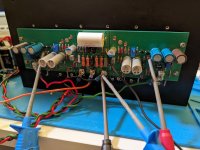
Wow that's a wonderful build - pretty much the same that I have planned, but I'm going for the 5.0 Turbo.The USSA-3 hybrid is alive and sounds very good. 🙂
First impressions: very good separation and soundstage, gives me that holographic sound with my speakers.
Bass is good, no need for higher damping factor.
So far it's the best amp I have built for my hifi-system.
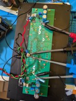
I've build it modular, even if there are only two modules 🙂
Power supply is easily inserted this way.
Build specs:
- LT4320 ideal bridges
- dual mono CLC PS, star ground
- GR grade for the SJ74/SK170, this gives 50% higher damping, I used 2k7 for R5/6 and 5k pots
- DC coupled, since I use a DC protection on the speaker out, I can live with the dangers of DC coupled and don't have the worry about the SQ of the coupling cap 😉
- bias at 1.3A
Thanks Fab, for this design !
1. How did you come to decided upon your specific choke type? I'm still debated chokes or capacitance multiplier (e.g. XRKs Smooth Like Buttah)
2. Any thoughts on adding bypass caps to the larger reservoir caps?
Thanks
A capacitrance multiplier always comes with a bit of a voltage drop, whereas a choke has very little voltage drop (if its DC resistance is low). If you design from scratch, you can just use a power transformer with a slightly higher secondary voltage spec to make up for the voltage lost across the cap multiplier. Once this is out of the way, I tend to prefer cap multipliers, because they are usually cheaper and smaller than an equivalent choke. I bulit my USSA with XRKs Smooth Like Buttah, which is not only a capacitance multiplier but also has an active rectifier to avoid the nasty switching noise. I highly recommend the SLB!1. How did you come to decided upon your specific choke type? I'm still debated chokes or capacitance multiplier (e.g. XRKs Smooth Like Buttah)
I was never able to measure anything with a scope, but my brain still says that bypass caps are good. I think the effect of bypass caps is mostly psychological (nothing wrong with that!).2. Any thoughts on adding bypass caps to the larger reservoir caps?

Excellent feedback @mbrennwa. My deliberation also comes from the consideration of running class A, vs high class A/B with the turbo like I am planning.
So as I understand it voltage drop = higher impedance. Now higher impedance is not really an issue into class A (because it’s constant current), but low impedance always sounds better with class A/B.
So how does this impact things?
Sorry for regurgitating commentary I’ve found here on the forums.
I have SLB PCBs ready to go… but also a source of very low DC resistance custom chokes.
If you add a capacitor bank of a couple of 22,000uF caps after the SLB and the amp, that should give you similar low impedance performance like an all C’s PSU normally seen on a Class AB. Best of both worlds - low ripple from Cap Mx and low impedance from the cap bank. If you want to go one extra, use one of those cap banks that uses 20x 1000uF caps in parallel. Typical 65mOhm ESR is now divided by 20 for 3.3mOhm ESR PSU. And to boot, 20x 1000uF caps is inexpensive. Just takes up more room.
I used such a cap bank here on a Class AB amp.

You can find kits on Aliexpress that do something similar for example 68x220uF (equivalent 15,000uF).
I used such a cap bank here on a Class AB amp.
You can find kits on Aliexpress that do something similar for example 68x220uF (equivalent 15,000uF).
Last edited:
The voltage drop across the capacitance multiplier has nothing to do with "impedance". The voltage drop provides some headroom to "eat" the ripple voltage from the the input voltage.So as I understand it voltage drop = higher impedance. Now higher impedance is not really an issue into class A (because it’s constant current), but low impedance always sounds better with class A/B.
The headroom for dynamic current variations with an A/B amp is mostly determined by the size of the capacitors at the PSU output. Just feed the smoothed DC output from the cap multiplier into some big capacitors and you're good.
Hi stretchneck,
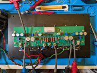
Yes, after building some amplifiers it finally came to this arrangement of the different parts and wiring,
the softstart is very nice, it keeps the AC mains relay switch on the back near the socket.
The chokes are made to specified specs by AEEtransformers,
for chokes you need low resistance < 0.1R, high DC current > 2A
and as much induction that you can have without getting too big in size, that will be about 5mH - 10mH
Attention: the chokes need to be specified for DC current!
Why chokes and not a capacitance multiplier like the SLB?
Because I already had the 2x18vac transformers, a capacitance multiplier would have dropped the voltages too much
Adding bypass caps to the larger reservoir caps is still on my todo list,
in a previous build I added them and I thought it sounded smoother, at least it will make you sleep better 🙂
Last edited:
Hello fellow USSA users! The power supply of my USSA5 developed a weird issue, and I am not sure if the mains transformer or the Smooth Liker Butter board is to blame. Since there are a few others here who used the SLB for their USSA amps I would be grateful to get some feedback on how your SLB / USSA combo worked out in the long run.
The details of my power supply problem are here: https://www.diyaudio.com/community/...x-class-a-power-supply-gb.336479/post-7280119
The details of my power supply problem are here: https://www.diyaudio.com/community/...x-class-a-power-supply-gb.336479/post-7280119
Hi Mbrennwa
sorry to hear that…. Unfortunately I have never used myself an SLB PSU…
Can you confirm that both USSA5 boards are still working fine using the still working power supply of the other channel so one USSA5 board has not caused the issue.
From the other linked thread, it is indeed unfortunate that both the transformer and SLB failed before triggering any protection but again I am not familiar with SLB detailed design….on my side (fingers crossed) I have never experienced a transfo failing….
keep us posted on your next finding.
Fab
That’s a bummer Mbrennwa.
I’ve used the SLB psu almost exclusively in all my Class A builds (including USSA5) since it was developed. I haven’t experienced a failed unit yet, knock on wood. Anand has some excellent advice and areas to look at in the SLB thread.
Good luck and post some pis of your setup to help you troubleshoot.
Done some prototyping and testing today.. It's singing right now. CMX onboard - dead-silent with some 93db/1W/1m-speakers. UMS compatible layout...
Attachments
Nice development progress nfsgame 😉
Is this an advancement from the USSA5 "turbo" you were working on last year?
Is this an advancement from the USSA5 "turbo" you were working on last year?
No it's a different animal I've talked with fab about before the turbo extensions were part of our discussion.
I also wanted to build a high power (with two pairs dual die lateral mosfets something like yours).
I ordered the components, resistors, latfets, caps, etc.
Just realized the JFets need to be cascaded because of the low voltage of the 2SJ74BL.
A BIT OUT OF MY LEAGUE because I am not familiar to simulate neither not set up with a scope.
After I ordered all the parts now the project got on hold for the mentioned reason.
I do not want to post the actual schematics here due to respect Fab's work!
It is the USSA 3, rew 2 with TWO pairs high power laterals.
If someone could help me with to CASCODE the J Fets it would be greatly appreciated!
Otherwise It may never be materialized as an amplifier all do I have the parts and layout made by me. The layout will be modified accordingly if someone could help with the circuit.
Thank you, Greetings
What exactly is your problem with the cascode?
Maybe you could share a schematic, and start a separate thread to discuss your design.
Maybe you could share a schematic, and start a separate thread to discuss your design.
To open a new thread would be nice if some of would come over to help, comment, etc.
Right now I have no problem with the cascode because there is none.
To explain my situation
Just found out the JFet 2sk74BL it has much lower voltage than the 2sk170BL.
That means I can not build the amp how I did planed without cascoding the front. And I ordered all the part plus design the layout.
We are talking about the USSA 3 Rew 2 with 2 pars of power mosfet and 36V rail voltage. Al Fet and JFet amplifier no bipolar in the circuit.
The 2SK170BL would be still OK at 36V but NOT the complementary the J74BL.
I would need some idea/help to implement a simple cascode to the JFets so the can work properly at 36V rail voltage.
Thank you!
Interesting project.
My understanding of nfsgame board pictures is that it may be a USSA5 Turbo (2 mosfet packages as output pairs ) pcb to match the Pass forum UMS heatsink mounting holes. There seems to be added parts , power supply related? Unless it is a cap multiplier or regulator circuit instead of double mosfet output ?
is that so?
I will contact him to understand more his objective….
Fab
Last edited:
Hi gaborbelaTo open a new thread would be nice if some of would come over to help, comment, etc.
Right now I have no problem with the cascode because there is none.
To explain my situation
Just found out the JFet 2sk74BL it has much lower voltage than the 2sk170BL.
That means I can not build the amp how I did planed without cascoding the front. And I ordered all the part plus design the layout.
We are talking about the USSA 3 Rew 2 with 2 pars of power mosfet and 36V rail voltage. Al Fet and JFet amplifier no bipolar in the circuit.
The 2SK170BL would be still OK at 36V but NOT the complementary the J74BL.
I would need some idea/help to implement a simple cascode to the JFets so the can work properly at 36V rail voltage.
Thank you!
the FSSA amplifier has the same jfet input stage as the USSA3 but with added input cascode (As an example of a possible way):
https://www.diyaudio.com/community/...-build-thread-with-review.350238/post-6103541
of course you would to adjust some values for 36VDC operation…
Fab
- Home
- Amplifiers
- Solid State
- USSA-5 Build with Review