I suggest using an LT4320 active rectifier with whatever psu you decide to use. They are more efficient, create no heat and IMO have sonic improvements over conventional based rectification, especially for Class A amplifiers. The SLB works extremely well with my USSA5.
I admit, I don’t know much about the LifePO4, how long would battery power last with a steady >2.5A draw from a stereo Class A amp?
I admit, I don’t know much about the LifePO4, how long would battery power last with a steady >2.5A draw from a stereo Class A amp?
I suggest using an LT4320 active rectifier with whatever psu you decide to use. They are more efficient, create no heat and IMO have sonic improvements over conventional based rectification, especially for Class A amplifiers. The SLB works extremely well with my USSA5.
I admit, I don’t know much about the LifePO4, how long would battery power last with a steady >2.5A draw from a stereo Class A amp?
Should last about an hour at 2.5A before the float charging kicks in... but is 2.5A a typical power draw at normal listening levels (with say 90dB sensitivity speaker)?
Just interested in this because LifePO4 batteries have some advantages with regards to noise and transient response.
Last edited:
Yes, once you flip a Class A amp power switch on, that baby is drawing a steady current of that particular amp design. Doesn’t really matter how efficient your speakers are or how loud your playing music. Actually, loud music lowers the heatsink temperature a degree or two.
I believe Fab spec’s 1.3A bias current per channel. 1.3 x2 =2.6A total.
I checked out that LifePO4 supply, pretty cool! Probably a better match for source and preamp duty. But, maybe a small Class AB amp??
I believe Fab spec’s 1.3A bias current per channel. 1.3 x2 =2.6A total.
I checked out that LifePO4 supply, pretty cool! Probably a better match for source and preamp duty. But, maybe a small Class AB amp??
Last edited:
Thanks - yes 1 hour is a little short, so it'd need 1 LifePO4 per channel. This would give just under two hours of run time. Of course playback would continue, its just that noise from the floating power supply would come through once charging commenced (so spec low noise SMPS). LifePO4 can be stacked.
FSSA with a PSU of +/-25Vdc gives 20Wrms / 8 ohms output, bias could be set to 800ma - run time would be around 3 hours.
Interesting...
FSSA with a PSU of +/-25Vdc gives 20Wrms / 8 ohms output, bias could be set to 800ma - run time would be around 3 hours.
Interesting...
One big problem stretchneck......
When you power up the USSA5, you don’t want to turn it off!! 😀
The FSSA is in my near future also, I was thinking the same 😉
When you power up the USSA5, you don’t want to turn it off!! 😀
The FSSA is in my near future also, I was thinking the same 😉
8.17.1 adjustment
Guys I have finally reached stage 8.17.1. after moving house and renovating.🙄
I adjust P1 for 50mV and then adjust P2 for 50mV.
The next step has me confused.
I randomly varied BOTH P1 and P2 and obtained zero volts offset on the output.
Results obtained for 23mA:
VGSP = 2.361V
RM3= 102.65
RV1= 55.65
RV1A =125.49
RV1B= 100
VGSN = 1.65V
RM4= 71.739
RV2= 24.739
RV2A= 52.23
RV2B= 47
I understand how the resistors are calculated but I have no confidence in how I zeroed the output offset.
Is there a proper method to do that or have I overlooked something???
Last edited:
Hi Harry
You have made good progress 🙂
For the dc offset, you may have overlooked but the manual states in section 9:
With no load on amplifier output (or load higher than 10K Ohms):
Output bias and dc offset are adjusted simultaneously using P1 and P2 pots;
Install the meter probe leads between TP1 and TP2(or TP3 and TP4);
Install another meter probes set between Output and Ground;
Turn P1 or P2 to center DC offset to < 5mV;
Turn P1 in one direction and then P2 about the same amount in same direction to increase (or decrease bias);
Turn P1 or P2 just a bit ( to prevent changing too much the bias) to re-center DC offset;
Wait until bias (temperature) stabilization (about 30 minutes) and readjust bias/DC offset if necessary;
Verify bias current between TP1/2 or TP3/4. Bias should be in the range of 1A to 1.3A (50mV to 65mV
with 0.05 Ohms) depending on your heatsink size and efficiency and power supply voltage. As the heatsink temperature rises, the bias will reduce, thus re-adjust when heatsink temperature is about <=50 deg C in the hottest section;
Re-adjust bias until at least 45 minutes;
Verify DC offset is below 5mV after temperature stabilisation. Re-adjust as necessary;
Steps may appear somewhat tricky but are standard for this type of symmetrical amplifiers.
The end results is about 50mv for 1A bias and about zero (<=5mv) dc offset. For 1.3A the voltage across source resistors is 65mv.
As for the VGSP and VGSN I am surprised they are that high for 1A bias (50mV)🙄
2.361V/(55.65+ 47) = 23ma : good
1.65V/(24.74 + 47) ohms = 23ma : good
Ensure, you measure 50mv between TP1/TP2 before measuring VGSP and VGSN.
Fab
Last edited:
Hi Fab,
Thanks for the reply. Wow I must be the only person here who cannot follow the 8.17.1 instructions.😱
I went back and set up TP4 to V- for 50mV using P1.
Then I adjusted TP2 to V+ for 50mV using P2.
I put one probe on the output and the other probe to PGND and measured -0.34 volts. This is too high.
The instructions say to re-adjust P1 and/ or P2 to obtain < 5mV.
This is where I am confused. I can adjust any one of the two trimmers to get to < 5mV???
So this is what I did - I turned P1 clockwise and I turned P2 anti clock wise, one turn at a time, until I got < 5mV.
If this is correct, the new results are:
VGSN = 1.088V
VGSP = 1.709V
IM3 = 0.011626 RV1A= 37.56 for 23mA
IM4 = 0.011574 RV2A= 0.306 for 23mA i.e. wire link
Last edited:
Hi Harry3
Do not get me wrong it is not that easy but when you practice you get the feel of it of balancing P1/P2 for bias and dc offset. Of course you have to turn P1and P2 in opposite direction when you overshoot from 0V dc offset. In the end you got it right!
Your new VGS values appears to be as expected.
keep on the good work! A few pictures of your assembly would be fun to look at😉
Good luck for the rest that should be quite easy ( burn-in and break- in).
Fab
Hi Fab
I finally had a chance to test out my USSA5 on my big rig. During Covid my work hours have been cut back, so more time to listen. The amp did a very nice job of driving my 4 ohm speakers. There was a nice deep sound stage and a lot of speed and excitement in it’s sound. I still need to do some more work to get the hum issue sorted. It is down around .4mv but that is still more than I like.
I need to re arrange the grounding between the input connectors and the 2 channel boards. I replaced the cooling fans but the ones I got are still A bit too noisy. They were cheap, so I though I would try them. I may try to put some sound absorption inside the lower portion of the chassis where the fans reside. It seems to resonate and be amplifying the noise. I would have been better off with one large fan turning at a slow speed than the 2 smaller ones I ended up with.
Brian
Hi Bfpca
At least one positive effect of the COVID...🙄
Thanks for the feedback 🙂
Your heatsinks are not big enough so you need a fan?
Noctua fan costs more but is more silent than other fans.
Fab
At least one positive effect of the COVID...🙄
Thanks for the feedback 🙂
Your heatsinks are not big enough so you need a fan?
Noctua fan costs more but is more silent than other fans.
Fab
Fan
Hi Bfpca,
I threw in a fan into my chassis for those hot days... and it was noisy.
If you put a zener in series with the fan it drops the voltage and the fan is quieter. See the attachment on how I wired it.
Note that doing this will reduce the airflow.
Hi Bfpca,
I threw in a fan into my chassis for those hot days... and it was noisy.
If you put a zener in series with the fan it drops the voltage and the fan is quieter. See the attachment on how I wired it.
Note that doing this will reduce the airflow.
Attachments
Last edited:
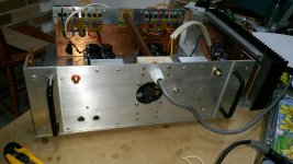
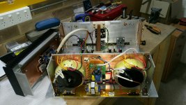
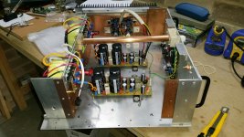
This is quite an implementation you have here. Copper plates, copper conduit for AC main line voltage, big PSU including capacitance multiplier, ....Thanks Fab. I have more confidence now.
Three different views of the amp I'm currently building. Cabling is temporary.
Mains cable goes through the copper pipe.😀
Keep us posted on the final assembly!
Fab
Wow, Nice work Harry3!
Looks like a “home brew” SLB with off board rectification. This will be one heavy USSA5 amplifier. Looking forward to viewing more of your progress 😉
Looks like a “home brew” SLB with off board rectification. This will be one heavy USSA5 amplifier. Looking forward to viewing more of your progress 😉
Chassis
Thanks guys.
It was a PAIN to make a chassis from scrap metal. At one stage, in my rush, I put a drill bit through one of the transformers. A costly mistake!😱
SLB boards are home made because of the prohibitive price to Australia and the exchange rate. I prefer the originals because they are much smaller.
Separate rectifier boards are used so I can compare them to a LT4320 based rectifiers. I was hoping to see comparisons on this thread.
The aluminium angle (left over from the home renovation) will hopefully take away some of the heat from the heatsinks and transfer it to the adjacent panels. I’m aiming for more than 1.3Amp bias as the voltage at the amp boards is around 22 volts, good for 4 ohm loads.
I avoided using any metal attracted to magnets. Screws and washers are stainless steel or nickel plated brass. Resistors used are Vishay CMF or RN because they do not use steel end caps. There are other brands as well that are not attracted to magnets.
The copper which I bought cheap, from a scrap metal yard that was closing down, makes the amp very, very heavy and hard to lift. Hence the handles on the back and I will put handles on the front panel when I finish. The chassis is large, so modifications are easily done. It might have been easier to make two mono amp chassis?
Hopefully I will finish the build soon (when my wife lets me)……🙄
Thanks Fab. I have more confidence now.
Three different views of the amp I'm currently building. Cabling is temporary.
Mains cable goes through the copper pipe.😀
Super dooper build. Now that put a smile on the face everytime it's lit up
Three different views of the amp I'm currently building. Cabling is temporary.
Any comments on the sound? What sources and speakers do you use?
Unfortunately I have yet to finish this amp as I am still renovating and doing most of the work myself. However there are a number of good reviews in this thread.
The front end comprises of a Marantz SA7001 SACD player, Technics SL1200 turntable and a custom PC with linear power suppliers and solid state drives. I’m currently looking for a good DAC.
I have a number of pre-amps - the USSPA is what I will build next.
Speakers are Curt Campbell’s Statements and Monitor speakers, a MTM and a small two way from electronic magazines.
If this amp isn’t “loud” enough, I will bi-amp the speakers. I have around 6 or more power amps that I have previously built, packed in boxes somewhere in the garage e.g. Borbely Wireless World, Krell, Destroyer X amps, Honey Badger, Slewmaster, etc… Eventually I will put three of these amps in different rooms.
I think that efficient and dynamic speakers like “The Loudspeaker or Faital 3WC “ by Troels Gravesen or the speaker that you built are very interesting and probably a very good match for this amp. Hopefully you can give us your review if/ when you complete this amp.
If only I had some spare cash🙄
- Home
- Amplifiers
- Solid State
- USSA-5 Build with Review