Great news !Good Sunday afternoon, I've just finished my PSU for my USSA-5 build, and completed and measured both channels. So I need just a few resistors in order to correct the drivers current to 20ma. 🙂 And I need a new R27 on one channel, because I fried it while taking off the crocodile clamps in an unproper way. 🙁
Beside that everything seems to be OK and I have to wait for the resistors. In the meantime the amp will move into its future chassis.
More to come.
Have a great Sunday!
Remember that 20ma driver current is for adjustment purpose at 1A output bias assuming that your final output bias will be more than 1,2 A . You can also target a little higher driver current such as 23ma for example.
Fab

Dear Fab,
Can I use 2SK1529 and 2SJ200 for output?
Thank you.
BR,
Josh
Not with this amp. Fab has another version which uses similar 2SK1530 & 2SJ201 Toshiba power mosfet. Be careful with those mosfets are rated only for medium (less) power.
Not with this amp. Fab has another version which uses similar 2SK1530 & 2SJ201 Toshiba power mosfet. Be careful with those mosfets are rated only for medium (less) power.
Yes that is right. Using vertical mosfet (even if these are good vertical mosfet for audio) instead of lateral MOSFETs would need design changes...
USSA1 and 2 use the mosfet you indicate. Even F5-USSA amp is a good candidate for your mosfet.
I can entertain an USSA5 type schematic with the 2SK1530 & 2SJ201 but that would be another thread subject and the sound result would be different too.
Fab
I am glad that you agree most of the part with me. I did not say that one amp is better than the other, i just made some evident observations.
I hope that helps future builders.
I did not changed the input capacitor yet...
Thanks you too, USSA is a great amp to own.
I hope that helps future builders.
I did not changed the input capacitor yet...
Thanks you too, USSA is a great amp to own.
Last edited:

Hi folks,
Please do not quote the entire post that you are responding to, just the relevant sections. Especially when that post is only a few before your post. Do not quote pictures.
-Chris
Great news !
Remember that 20ma driver current is for adjustment purpose at 1A output bias assuming that your final output bias will be more than 1,2 A .
Fab
Hi Fab, I wanna keep the current at about 1A. I have 100 db /W 16 Ohm speaker, so I a low power rating is sufficient. Could go even lower I guess....
Cheers, Ernst
If you run at 1A output final bias then you should target about >=25ma for driver current. The goal is to operate the driver in a more linear region.
Fab
Fab
Last edited:
I was lucky enough to buy a USSA-5 kit in November that was a left over from the earlier QuebecDIY forum group buy (thanks Do).
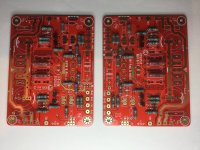
I promised Fab that I would update as I made progress, so here is the first. These are the version 0.1 boards in glowing red. Most of the small resistors are in (though I made a mistake on my last order and shorted myself a couple of 220R, so testing will have to wait until I can get more)). Some of the larger resistors, small diodes and jfets are in too.
Question for Fab: capacitor C1 (220 pF mica in the kit). The mica leads are too big and would have to be soldered to the top of the pads, per Do's suggestion. I have some extra 240 pF polystyrene that would go through hole and wondering if these would be appropriate in this position?
Thanks!
Attachments
Hi Everyone,
My heatsink from Conrad Engineering has arrived, Is there a Mouser BOM here that i can use to order all the components ?
My heatsink from Conrad Engineering has arrived, Is there a Mouser BOM here that i can use to order all the components ?
Hi Johnny
I have not used polystyrene cap since a long time... I would still use the mica since it is not a big deal to install. Version 0.4 of pcb have increased size holes for that cap.
Thanks for your update.
Fab
I have not used polystyrene cap since a long time... I would still use the mica since it is not a big deal to install. Version 0.4 of pcb have increased size holes for that cap.
Thanks for your update.
Fab
Last edited:
Last edited:
Hi Fab,
I got a pair of your PCBs from my friend. USSA5.0 Rev0.4
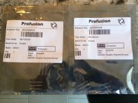
May i know where can i find the power Mosfets?
ALF16P16W
ALF16N16W
They are no longer available in Mouser/Digikey and ELement/Farnell.
I got a pair of your PCBs from my friend. USSA5.0 Rev0.4
May i know where can i find the power Mosfets?
ALF16P16W
ALF16N16W
They are no longer available in Mouser/Digikey and ELement/Farnell.
Last edited:
12V offset
Hi Fab,
meanwhile I have I have changed the reisistors R13/R14 on both channels in order to have about 26ma drivercurrent.
One channel is working very well, I could set bias to 1A, offset ist below 2mV 🙂
The second channel shows 12V offset after resistorchange and I have no idea, why that could be. This offset cannot be reduced under about 9V by adjustment of P1/P2.
Any idea, what this could be?
Cheers Ernst
Hi ErnstHi Fab,
meanwhile I have I have changed the reisistors R13/R14 on both channels in order to have about 26ma drivercurrent.
One channel is working very well, I could set bias to 1A, offset ist below 2mV 🙂
The second channel shows 12V offset after resistorchange and I have no idea, why that could be. This offset cannot be reduced under about 9V by adjustment of P1/P2.
Any idea, what this could be?
Cheers Ernst
I am glad you have one channel fine.
For the other channel, you can redo the test sections (8.7, 8.8.5, 8.14, 8.17, 8.18) of the manual with pcb fully populated and provide results for each. I need more info. Ensure you have both ground terminals of the pcb connected to PSU. Check for any solder bridge or cold solder joints. Check for shorted diodes close to mosfet gate. Check driver VGS which should be about 2 to 2.4 volts.
Fab
Last edited:
- Home
- Amplifiers
- Solid State
- USSA-5 Build with Review