Re: actually, ....
No, it would create 2nd-order filter, possibly with high Q hence peaky roll-off.
FastEddy said:I believe that an industor at R1A (et al) would do the reverse of "resonate", since it would effectively become a very low pass filter, allowing only DC to pass ... L / C filter instead of R / C ...
No, it would create 2nd-order filter, possibly with high Q hence peaky roll-off.
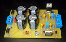
ezkcdude said:You can see I need more soldering practice. This is the first time I have soldered a PCB. I started on the right side, and improved as I got to the other components.
Good job - but you will need to go over some of those early joints as some appear to be dry
Hi,
soldering a component leg into a large copper plane is not easy.
Setting the soldering iron to a higher temperature and using a bit with more mass (thermal inertia) both help. A well wetted chisel tip placed first on the copper plane to heat the PCB but very close to the compnent and adjusted by sliding the tip to contact the leg usually allows the PCB to gain sufficient heat to melt the solder adequately but without overheating the component.
At the board layout stage, a modfied technique helps significantly. A small land is placed around the leg surrounded by a moat of bare PCB substrate. Four short legs of copper connect like bridges between the land and the plane. This feature might exist as an option in the PCB software.
Well done Ezk, order 10 boards (or maybe 20 if your hooked) now that you know it works. You'll find uses for them all eventually.
AndrewT said:Hi,
soldering a component leg into a large copper plane is not easy.
Setting the soldering iron to a higher temperature and using a bit with more mass (thermal inertia) both help. A well wetted chisel tip placed first on the copper plane to heat the PCB but very close to the compnent and adjusted by sliding the tip to contact the leg usually allows the PCB to gain sufficient heat to melt the solder adequately but without overheating the component.
Thanks, for the tip. I actually sort of realized this as I was doing it. I assume by "wetted" you mean with solder, because that's essentially what I was doing. I also realized that when I started to see the rosin flow out of the solder, that it was a good sign to look for to make sure the joint was o.k.
As for ordering more boards, I will probably wait on that for now. Currently, I'm using ExpressPCB, but it might behoove me to learn Eagle Light (I can't afford the full package right now), and redesign the PCB using that. That way I can have more flexibility in choosing the board manufacturer. Although, I must say I think (not having a wit of experience) that the Express PCB board looks pretty nice to me.
- Status
- Not open for further replies.
- Home
- Amplifiers
- Power Supplies
- Using unregulated AC wall wart