Some time ago I had seen a variation of an LM317/337 power supply in The Audio Amateur but applied for higher voltages that it was designed for.
In theory, the LM317/337 regulators, as well as the LT1083, accept up to 37v inputs. But in fact what it can't accept is a 37v difference between input and output.
So you can feed higher voltage at the regulator's input as long as the difference with the output voltage does not exceed 37v. Right?
What you does lose is protection, particularly from output short-circuit.
If I remember well, and that is what I am asking a suggestion for, what you had to use was to add a zener diode voltage between the regulator's output and input. If I remember well that zener was between 37v and 39v.
Do you agree with such a regulator as safe to use?
In that TAA article the regulator was used on a Hafler power amp, feeding a higher regulated voltage to the low current stages, leaving just the power output unregulated.
Most amplifiers use such a solution, but sometimes the regulator they used there is not that good, and I think a 317/337 pair would work well.
What do you think? What would you suggest?
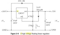
That topology wants a current limited main supply to be robust - 1W zener isn't going last long on overload. Perhaps use it to drive an emitter-follower transistor (on the heatsink)?
There is nothing wrong with using the LM317 or LM317HV for high voltage, as long as you accept that it will fail if shorted. The zener just helps ensure the LM317 regulates properly, not survive a short.
I think that at startup when the output cap is at 0Volts the LM317 sees the entire 100 volts. The Zener quickly charges the cap to 100-39 and protects the LM317. I use the same setup to supply a LME49830 Fet amp front end with +/- 75 VDC and the output vertical fets are at +/- 65VDC.

I'm trying to follow certain findings published in The Audio Amateur in the '90s about the impedance curve of regulators. Not many regulators publish that data, Texas does not on the 783, for instance.
Yes, many regulators, like the LT1083, do not have a negative version, so you need to have separate secondaries on the transformers, wiring them after the regulation and using the ground on one regulator as negative output.
But I would like to have an advice on how to implement my regulator with the 317 or 1083 if possible, just warning what would remain unprotected, like short-circuiting the output, which would be quite rare to happen and would allow me to use them.
My main concern is protection for what I am to power with those regulators.
Exxxxxxtremely complicated!!! I want something simpler but high quality, preferably with a proven regulator like the 317/337.
If I wanted something like the Maida I would go with a Sulzer or Jung high voltage regulator. It would be just a question of finding a high voltage IC, and that would be hard to beat.
Those are proven designs, both technically and audio wise.
If I wanted something like the Maida I would go with a Sulzer or Jung high voltage regulator. It would be just a question of finding a high voltage IC, and that would be hard to beat.
Those are proven designs, both technically and audio wise.
You can't have it both ways.
I do not know why you want to complicate the issue with wanting 'impedance curve of regulators" If you want them, measure them yourself.
OVP, use a SCR crowbar.
OCP use a fusible R or an actual fuse in front of or use a current limiting circuit in front of the reg.
I do not know why you want to complicate the issue with wanting 'impedance curve of regulators" If you want them, measure them yourself.
What kind of protection?My main concern is protection for what I am to power with those regulators.
OVP, use a SCR crowbar.
OCP use a fusible R or an actual fuse in front of or use a current limiting circuit in front of the reg.
The protection I mean is for overvoltage at the output.
Which high voltage IC would anyone suggest to use on a HV Jung/Didden regulator?
Some time ago one was suggested to me, but I forgot which it was.
Which high voltage IC would anyone suggest to use on a HV Jung/Didden regulator?
Some time ago one was suggested to me, but I forgot which it was.
The only I could find googling was this one:
http://www.ti.com/product/OPA454
But current is too low to be used on a power amp, even in the low current stages.
Neither if it would be a good choice for superregulator.
http://www.ti.com/product/OPA454
But current is too low to be used on a power amp, even in the low current stages.
Neither if it would be a good choice for superregulator.
OVP, use a SCR crowbar.The protection I mean is for overvoltage at the output.
Show me a " HV Jung/Didden regulator" schematic
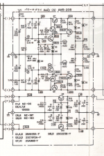
I found this HV dual tracker from Pioneer a while ago.
Attachments
Last edited:
These used to be quite common at the time. This one would seem to be high performance (thumbs up for the current source and AC unity gain) but has a few quirks:I found this HV dual tracker from Pioneer a while ago.
1. I wonder why they used a CFP for a pass transistor when there was ample voltage headroom?
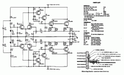
2. Also, why this peculiar voltage adjustment setup with one resistor chain for both and an extra pot for symmetry? Most looked more like this (from a Sansui AU-717):
I.e. the the -reg is basically an inverting amplifier with a DC gain of roughly -1 (allowing for a -0.6 V offset, occasionally also provided by a diode so they could use equal resistor values - it's not like utmost precision is required here), based on the +reg doing its own thing.
The Pioneer design was out of the norm for sure, that is why I posted it because I saw it was different and from one of their TOTL models at the time, M-Z1.
I can not answer your ?'s as to why it was done that way, only speculation. Would need to simulate to figure out performance but I will leave that to the op.
This Sansui design was more common for sure. No protection other than fuses. The tracking saved them a zener.
I can not answer your ?'s as to why it was done that way, only speculation. Would need to simulate to figure out performance but I will leave that to the op.
This Sansui design was more common for sure. No protection other than fuses. The tracking saved them a zener.
OK, I don't have here the high voltage regulators suggested in The Audio Amateur, as I am not at home.
The ones I was referring to, based on the 3X7 regulators, were used for an Erno Borbely 60W amp mod, and also for a Hafler DH220. Perhaps someone might remember them.
But I was thinking of a different, more sophisticated and more expensive approach: a high current Jung/Didden superregulator.
Some time ago I had also asked here about such a regulator, and Jan Didden had suggested a high voltage opamp that I can't remember which it was.
Looking around for high voltage suitable opamps, the only one I could find was this one:
OPA552PA Texas Instruments | Integrated Circuits (ICs) | DigiKey
Unfortunately I would need a higher voltage chip, as the amp I would use it for would need +/-67v. The OPA552 can only go up to +/-30v, that means +60v should be the maximum input voltage, which would mean less than 55v DC for the output. Am I correct?
It's a pity I never saw a voltage regulators comparison that included the Kit Ryan's regulator used for the Adcom GFA555. Here it's the high current version they used for it, but Nelson Pass used it to regulate the low current stages on his A75 power amp.
Attachments
- Home
- Amplifiers
- Power Supplies
- Using the LM317 with higher voltages