Salas, need some help with the shunt reg.
I did as per your instructions in the first post. I'm having trouble with the neg reg. My target is 30V, 140ma.
I installed 3 47R resistors at R1, giving 15.7R total. Voltage across R1 is 2.8, giving 178ma, slightly high. Here are the other voltages
220R - 1.62V
10R - 37.5mV
Vout - 5.78V
Going through the calculations, we get 4.6V as base voltage, requiring the addition of 25.4V. Vref current is 3.75mA, and the required resistor would be 6.77k. I hope this is correct!
When I installed this resistor, I get Vout of 13.4V. Checked solder joints, everything looks fine. On the neg side, the Vref LEDs are kinda dim. Any idea what's going on?
On the positive reg, I got similar results, except there is 51mV across 10R. After calculation, I get a 5k resistor, which gives me close to 30V.
Last edited:
Salas
I like to use film cap - better sounding - not lytic at Vref filter and V out
what Is the lower value for Vref cap that you can recommend to use if we have say 2 - 5 leds
why Is so important to have big value
can we reduce also V out cap value
what about 1 - 4 uF at Vref filter and V out
which Is more Important to be high Vref filter or V out value
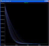
The Leds Vref bypass capacitor is directly affecting noise filtering. Depends on how sensitive the application is to that. A line buffer obviously is much more indifferent than a 1500 times gain MC phono stage, a clock is susceptible to very low frequency noise etc. Here is a stepped noise simulation for 5uF to 100uF (more capacitance as you go to the left most curve). The output one don't touch it, it is calculated as it is for stability.
Attachments
thank you Salas
great reply
but from simulation I see that noise level Is already very low
can we perceive difference 5 uF and 100 uF
I like TO 247 devices very much - they can be cooled easier so Is It possible to use at least one of them In BIB
are the difference between BIB and hypno regulator sense output and bandwidth
3 differences. Vref is LEDS, sense, bandwidth. Noise gets spread if integrated over frequency. Film Vref caps OK for line level applications PSU.
Hypnotize regs for crossover
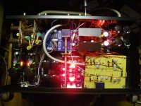
I finished my year long project: Salas simple phono pre amp, Mesmerize DCB1, and 24db/octave 2 way crossover powered by 2 Hypnotize regulators all in the same box.
The link below will take you to the design and my implementation.
The box just kept getting smaller and smaller as this project continued.
http://www.diyaudio.com/forums/pass-labs/156094-b1-active-crossover-26.html#post3185663
Thank you Salas for your designs and all your help and the helpful posts of each builder.
I am very happy with how it sounds.
On to the F5T and F6.
Rush
Attachments
You are welcome. The combo can be even more impressive if you will ever hook it up to a 28dB+ gain amp. Then the system gain with phono as a source will reach its full potential. Depends on speakers sensitivity a lot though. Happy listening.
Salas
I have FC 100 uF at Hypno Vout
If I power D1 I/V which have 100 - 220 uF local decoupling do I need to lower local decoupling value or have to add series resistance
coupling wires are 10 - 12 cm
I have FC 100 uF at Hypno Vout
If I power D1 I/V which have 100 - 220 uF local decoupling do I need to lower local decoupling value or have to add series resistance
coupling wires are 10 - 12 cm
See if the system as a whole is still stable with 47uF at the Hypno's local termination. And if you like it better also.
I will remove local load decoupling caps
Isn't It 100 uF Hypno local termination - that value Is taped on a pcb mask
Isn't It 100 uF Hypno local termination - that value Is taped on a pcb mask
If I use separate external full wave rectification and separate transformers to supply +28VD and -8VDC to the regulators' inputs, can I get 24VDC and -3.3VDC regulated outputs? I have the Mezmerize version by crt.
24VDC should of course be no problem, but will I have to make the negative output lower in voltage? Like -5VDC regulated, and then bring the voltage down with an additional CRC filter, or can I get -3.3V directly?
24VDC should of course be no problem, but will I have to make the negative output lower in voltage? Like -5VDC regulated, and then bring the voltage down with an additional CRC filter, or can I get -3.3V directly?
You may try -3.3V directly by substituting an NPN pin compatible BJT in the place of the output Mosfet. That will be rather safe for stability after changing the gate resistor to an order of magnitude lower for base stopper and using one of the better beta transistors. I would make sure all is quiet by looking at that rail with the scope. The Vref area should be calculated at 0.6Vbe+IxR in its JFEt tail resistor plus a red led and a diode or so. See post 1. Whatever brings 3.3V total across in other words. From your available Vin to Vout stated its a bit tight though, don't know if your mains would stay there always. The reg can regulate LDO style, its just the CCS it will not be at its best without a good margin of input to output voltage.
Better use 3 red LED instead of a Zener in the CCS. Less noisy.
Oh, I should have added that the Zeners are just for simulation purposes.
But thank you for pointing it out, you never know...
- Status
- Not open for further replies.
- Home
- Amplifiers
- Power Supplies
- Using the HYPNOTIZE as a general shunt reg PCB